
1. Introduction
The Taidacent HP363 RF Power Meter is a compact and reliable device designed for radio frequency power measurement and instrument calibration. It features a simple structure, convenient operation via buttons, stable performance, high sensitivity, and fast measurement speed. This manual provides detailed instructions for the proper setup, operation, and maintenance of your HP363 RF Power Meter.
Key features include:
- Measuring power range: -50 dBm to +0 dBm (extendable to 100 dBm with an external RF attenuator).
- Measuring power resolution: 0.1 dBm.
- Frequency range: 1 MHz to 10 GHz.
- Power measurement range: 1 nW to 1 mW.

Figure 1: Overview of the Taidacent HP363 RF Power Meter module with its LCD display.
2. Setup Instructions
Before operating the HP363 RF Power Meter, ensure proper connections for power and RF input.
2.1 Components Overview

Figure 2: Top view of the HP363 circuit board. Note the P1 (power), P2 (RF input), and control buttons (FUN, MODE, SEL).
2.2 Power Connection
- Locate the P1 terminal block on the circuit board. This is labeled "VDD" and "GND".
- Connect a stable DC power supply to the P1 terminal. The recommended operating voltage is 7V to 12V DC. Ensure correct polarity: VDD to positive (+) and GND to negative (-).
- Verify the power supply is within the specified voltage range to prevent damage to the device.

Figure 3: Close-up of the power input (P1) and RF input (P2) connectors.
2.3 RF Input Connection
- Identify the P2 connector, which is an SMA female connector, labeled "P2 Input".
- Connect your RF signal source to the P2 SMA input using an appropriate SMA cable.
- If measuring power levels above 0 dBm, an external RF attenuator is required. Connect the attenuator between your RF source and the P2 input. The device can measure up to 100 dBm with suitable external attenuation.
2.4 LCD Display Connection
The HP363 module typically comes with a 1602A LCD display. Ensure the 16-pin header on the main board is correctly aligned and connected to the corresponding pins on the LCD module.

Figure 4: The main board and LCD display module shown separately, highlighting the connection interface.
3. Operating Instructions
The HP363 RF Power Meter is operated using three push-buttons: FUN, MODE, and SEL.
3.1 Powering On and Initial Display
Once power is supplied, the LCD display will illuminate and show the current measurement or setting. The default display often shows "RF Attenuator ADD 0.0dB" or the current power reading.
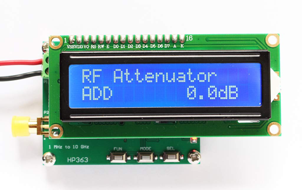
Figure 5: The LCD display showing the attenuator setting.
3.2 Button Functions
- FUN (Function) Button: Typically used to cycle through different measurement modes or settings. Pressing this button may switch between power measurement, frequency display, or other available functions.
- MODE Button: Used to select specific parameters within a chosen function. For example, in attenuation setting mode, it might switch between adjusting the integer part and the decimal part of the attenuation value.
- SEL (Select/Adjust) Button: Used to increment or decrement values, or to confirm a selection. When setting attenuation, this button will adjust the displayed value.
3.3 Setting External Attenuation
If you are using an external RF attenuator, it is crucial to set its value in the power meter for accurate readings.
- Press the FUN button until the display shows "RF Attenuator ADD" or a similar attenuation setting screen.
- Use the MODE button to select which digit or part of the attenuation value you wish to adjust (e.g., integer part, decimal part).
- Use the SEL button to increase or decrease the selected value.
- Once the correct attenuation value is set, press FUN again to save the setting and return to the measurement mode.
Note: The device automatically compensates for the set attenuation value in its power readings. Ensure this value matches your physical external attenuator.
3.4 Power Measurement
After setting up the attenuation (if applicable) and connecting the RF input, the device will display the measured power in dBm.
- Ensure your RF source is active and connected to P2 Input.
- The display will show the real-time power measurement.
- The measurement range is -50 dBm to +0 dBm directly. For higher power, use an external attenuator and set its value as described above.
4. Maintenance
Proper maintenance ensures the longevity and accuracy of your Taidacent HP363 RF Power Meter.
- Cleaning: Use a soft, dry cloth to clean the device. Avoid using liquid cleaners or solvents, as they can damage the electronic components.
- Storage: Store the device in a dry, dust-free environment away from direct sunlight and extreme temperatures.
- Handling: Handle the circuit board with care to avoid damaging components or connections. Avoid static discharge when handling.
- Connectors: Keep the SMA connector clean and free from debris. Use protective caps when not in use.
5. Troubleshooting
If you encounter issues with your HP363 RF Power Meter, refer to the following common problems and solutions:
| Problem | Possible Cause | Solution |
|---|---|---|
| No display on LCD |
|
|
| Incorrect power readings |
|
|
| Buttons unresponsive |
|
|
6. Specifications
| Parameter | Value |
|---|---|
| Model | xdlhp636 |
| Brand | Taidacent |
| Measurement Type | Power Meter |
| Frequency Range | 1 MHz to 10 GHz |
| Measuring Power Range | -50 dBm to +0 dBm (extendable to 100 dBm with external attenuator) |
| Measuring Power Resolution | 0.1 dBm |
| Measuring Power | 1 nW to 1 mW |
| Minimum Operating Voltage | 7 Volts (DC) |
| Maximum Operating Voltage | 12 Volts (DC) |
| Upper Temperature Rating | 65 Degrees Celsius |
| Item Weight | 0.01 Ounces |
| Certifications | CE, NIST, RoHS |

Figure 6: Dimensions of the HP363 module.
7. Warranty and Support
For warranty information or technical support regarding your Taidacent HP363 RF Power Meter, please refer to the documentation provided at the time of purchase or contact Taidacent customer service directly. You may also visit the official Taidacent store on Amazon for additional resources and contact options: