1. Introduction
This manual provides instructions for the installation, operation, and maintenance of the Walfront PID REX-C100 Digital Temperature Controller Kit. This kit is designed for precise temperature control in various applications, offering both heating and refrigeration modes. It includes a digital temperature controller, a K-type thermocouple probe, and a 40A Solid State Relay (SSR).
The controller features a clear digital display for process value (PV) and set value (SV), along with LED indicators for output and alarm status. Its robust design ensures reliable performance in diverse environments.
2. Package Contents
Verify that all components are present and undamaged upon unpacking:
- 1 x Walfront PID REX-C100 Digital Temperature Controller
- 1 x K-Type Thermocouple Probe Sensor (1 meter length)
- 1 x Max. 40A Solid State Relay (SSR)
- 1 x Mounting Bracket for Controller

Image 2.1: The complete Walfront PID REX-C100 Temperature Controller Kit, showing the controller, Solid State Relay (SSR), K-type thermocouple, and mounting bracket.
3. Specifications
3.1. REX-C100 Temperature Controller
- Measuring Accuracy: ±0.5%FS
- Cold-end Compensation Tolerance: ±2℃ (modifiable by software in 0~50℃)
- Resolution: 14 bit
- Sampling Cycle: 0.5 seconds
- Power Supply: AC100-240V
- Display: Process Value (PV), Setting Value (SV) via LED
- Control Method: PIN control (ON/OFF, step-type PID, continuous PID), Self-tuning control
- Relay Output: Contact capacity 250V AC 3A (resistive load)
- Proportional Band (P): 0~full range (ON/OFF control when set to 0)
- Integral Time (I): 0~3600 seconds (No integral action when set to 0)
- Derivative Time (D): 0~3600 seconds (No derivative action when set to 0)
- Heat-reset Proportional Cycle: 1~100 seconds
- Insulation Resistance: >500M ohm (500V DC)
- Dielectric Strength: 1500V AC/min
- Power Consumption: 10 VA
- Service Environment: 0~50℃, 30~85% RH (non-corrosive gas environment)
- Product Dimensions: 5.51 x 2.76 x 2.36 inches
- Item Weight: 8.8 ounces

Image 3.1: Front view of the REX-C100 controller with its physical dimensions indicated.
3.2. K Thermocouple Probe Cable
- Length: 1 meter
- Sensor Diameter: 4.5mm
- Temperature Range: 0-400℃
- Internal Insulation: Fiberglass
- External Shielding: Insulated Shielding
3.3. Max. 40A Solid State Relay (SSR)
- Output Current: 40A
- Input Voltage: DC 3-32V
- Output Voltage: 24-380VAC

Image 3.2: The GD 40A Solid State Relay (SSR) included in the kit, showing its input and output terminals.
4. Safety Information
Please read and understand all safety instructions before installing or operating this device. Failure to follow these instructions may result in electric shock, fire, or personal injury.
- Electrical Hazard: This device operates with high voltage. All wiring should be performed by a qualified electrician or knowledgeable individual. Ensure power is disconnected before making any connections.
- Proper Grounding: Ensure the device and any connected equipment are properly grounded.
- Ventilation: Install the controller in a location with adequate ventilation to prevent overheating.
- Environmental Conditions: Do not expose the device to moisture, corrosive gases, or extreme temperatures outside its specified operating range.
- Load Capacity: Do not exceed the maximum current and voltage ratings of the Solid State Relay (SSR) or the controller's output.
5. Installation and Wiring
Proper installation and wiring are critical for the safe and effective operation of the temperature control system. Refer to the wiring diagram on the back of the controller for specific terminal connections.

Image 5.1: Wiring diagram label on the back of the REX-C100 controller, detailing connections for power, sensor, and output.
5.1. Controller Mounting
The REX-C100 controller is designed for panel mounting. Use the provided mounting bracket to secure the controller into a cutout of appropriate dimensions.

Image 5.2: Front view of the REX-C100 Digital Temperature Controller, showing the display and control buttons.
5.2. Wiring Connections
Refer to Image 5.1 for the terminal layout. Ensure all connections are secure and correctly polarized where applicable.
- Power Supply (Terminals 1 & 2): Connect AC100-240V power to these terminals.
- K-Type Thermocouple (Terminals 8 & 9): Connect the K-type thermocouple probe to these terminals. Ensure correct polarity (positive to positive, negative to negative) for accurate readings.
- Solid State Relay (SSR) Output (Terminals 4 & 5): These terminals provide the control signal (DC 3-32V) to the SSR. Connect Terminal 4 to the negative input of the SSR and Terminal 5 to the positive input of the SSR.
- SSR Load Connections: Connect the load (e.g., heating element) to the output terminals of the 40A SSR. Connect the main AC power supply to the SSR's input terminals. Ensure the load's current and voltage requirements do not exceed the SSR's ratings.
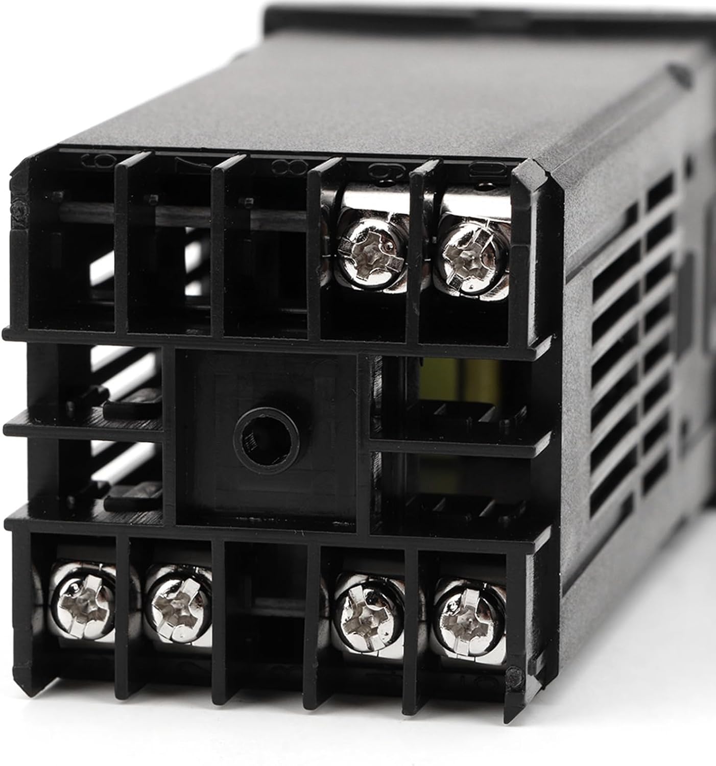
Image 5.3: Rear view of the REX-C100 controller, showing the screw terminals for wiring connections.
6. Operation
Once wired and powered on, the controller will display the current process value (PV) and the set value (SV).
6.1. Basic Temperature Setting
- Press the SET button once. The SV display will begin to flash.
- Use the Up (▲) and Down (▼) arrow buttons to adjust the desired temperature (SV).
- Press the SET button again to confirm the new SV. The display will stop flashing, and the controller will begin to regulate the temperature to the new set point.
6.2. Advanced Settings (PID Parameters)
To access advanced settings for PID tuning, press and hold the SET button for approximately 3-5 seconds until the parameter menu appears. Use the SET button to cycle through parameters and the arrow buttons to adjust values. Refer to the controller's detailed programming manual (if available) for specific parameter definitions and tuning procedures.
- Self-Tuning: The controller supports self-tuning control to optimize PID parameters for your specific application. Activate self-tuning from the advanced settings menu.
- Heating/Refrigeration Mode: The controller can be configured for either heating or refrigeration control. This setting is typically found in the advanced parameter menu.
- Compressor Delay Protection: For refrigeration applications, a compressor delay protection function is available to prevent rapid cycling of the compressor.
7. Maintenance
The Walfront PID REX-C100 Temperature Controller Kit requires minimal maintenance. Regular checks can ensure optimal performance and longevity.
- Cleaning: Clean the controller's display and casing with a soft, dry cloth. Do not use abrasive cleaners or solvents.
- Connections: Periodically check all wiring connections for tightness and signs of corrosion.
- Ventilation: Ensure the ventilation slots on the controller are not obstructed to allow for proper heat dissipation.
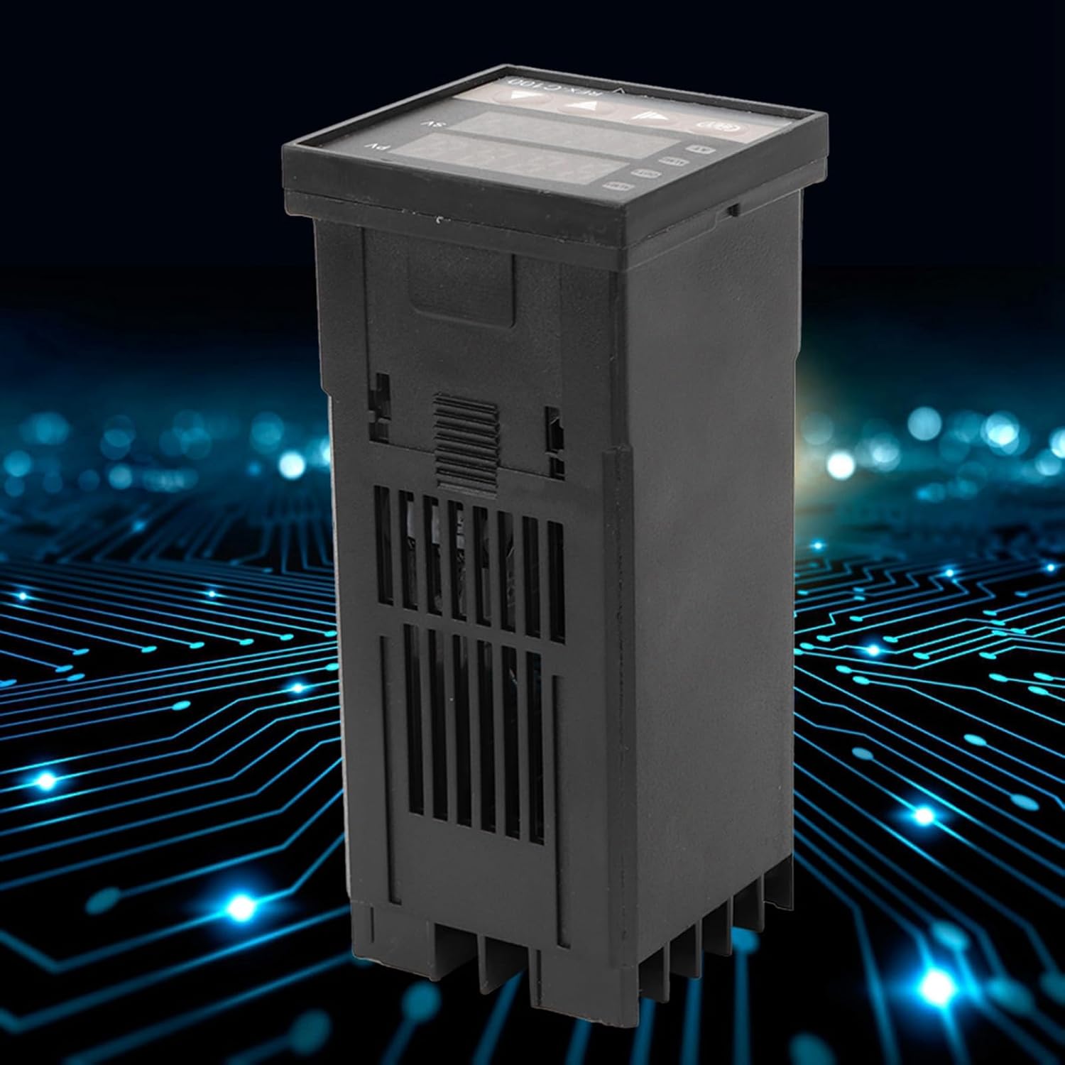
Image 7.1: Side view of the REX-C100 controller, showing the ventilation slots.
8. Troubleshooting
If you encounter issues with your Walfront PID REX-C100 Temperature Controller Kit, refer to the following common problems and solutions:
| Problem | Possible Cause | Solution |
|---|---|---|
| Controller does not power on | No power supply; incorrect wiring; faulty unit | Check power connections (Terminals 1 & 2). Verify power source. Inspect wiring for shorts or breaks. |
| Inaccurate temperature reading (PV) | Thermocouple not connected; incorrect thermocouple type; reversed polarity; damaged thermocouple | Ensure K-type thermocouple is correctly connected to Terminals 8 & 9 with correct polarity. Check thermocouple for physical damage. |
| Output (SSR) not activating | Incorrect wiring to SSR; faulty SSR; controller settings (SV, PID parameters) | Verify wiring between controller output (Terminals 4 & 5) and SSR input. Check SSR input voltage. Ensure SV is set correctly and PV is outside the desired range to trigger output. Test SSR independently if possible. |
| Temperature overshoots/undershoots | PID parameters not tuned; incorrect control mode | Perform self-tuning or manually adjust PID parameters (P, I, D) in the advanced settings. Ensure the correct control mode (heating/refrigeration) is selected. |


