
1. Introduction
The BTMETER BT-5900A is a versatile wire tracker and tone generator designed for testing and tracing various types of cables. This device is suitable for identifying telephone lines, network cables (RJ11, RJ45), and other low-voltage electrical wires. It assists in locating cables, checking continuity, and verifying line status in complex electrical networks.

Image 1.1: The BT-5900A Wire Tracker being used to locate cables in a network environment.
2. Product Overview
2.1 Components
The BT-5900A system consists of a transmitter (tone generator) and a receiver (probe). Familiarize yourself with the components and their functions:

Image 2.1: Transmitter (Tone Generator) Components. Key parts include the RJ11/RJ45 ports, power switch, test key, and status indicators.

Image 2.2: Receiver (Probe) Components. Key parts include the probe tip, volume knob, scan button, light switch, and power switch.
2.2 Key Features
- Multi-Task Cable Tracing: Ideal for telephone line testing, network cable tracing, and other weak current electric wires.
- Network Cable Testing: Detects open circuits, short-circuits, miss-wiring, error connections, and reverse connections.
- Telephone Line Status: Accurately tests the working status of telephone lines (idle, ringing, disconnecting).
- Line Level and Polarity Test: Identifies line level and positive/negative polarity.
- Integrated Lighting: Built-in lamp on the receiver for use in dark environments.
- Adjustable Audio: Volume knob on the receiver to adjust signal sensitivity.
- Earphone Jack: For use in noisy environments.
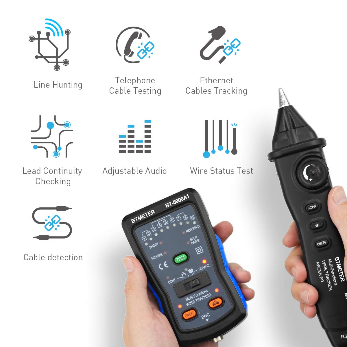
Image 2.3: Visual representation of the BT-5900A's multi-functional capabilities.
3. Setup
3.1 Package Contents
Before starting, ensure all components are present in the package:
- BT-5900A Transmitter
- BT-5900A Receiver (Probe)
- RJ11 Cable
- RJ45 Cable
- Alligator Clip Adapter Cable
- Earphone
- Carrying Pouch
- User Manual
- Batteries (if included)

Image 3.1: All items included in the BT-5900A product package.
3.2 Battery Installation
- Locate the battery compartment on both the transmitter and receiver units.
- Open the battery cover.
- Insert the required batteries, ensuring correct polarity (+/-).
- Close the battery cover securely.
4. Operating Instructions
This section details the various functions of the BT-5900A and how to use them.
4.1 Network Cable Tracing (RJ45)
- Connect one end of the RJ45 cable to the RJ45 port on the transmitter.
- Connect the other end of the RJ45 cable to the network port you wish to trace.
- Turn on the transmitter by sliding the power switch to the 'ON' position.
- Turn on the receiver by pressing the 'ON/OFF' button.
- Adjust the receiver's volume knob to a suitable level.
- Press the 'SCAN' button on the receiver and move the probe tip near the suspected cables. A distinct tone will indicate the target cable.
- For network cable continuity testing, select 'TEST' mode on the transmitter. The indicator lights will show the wiring status (short, open, miswire, etc.).
Video 4.1: Official instruction video demonstrating the use of the BT-5900A Wire Tracker Tone Generator for network cable testing.
4.2 Telephone Line Testing (RJ11)
- Connect the RJ11 cable to the RJ11 port on the transmitter.
- Connect the other end of the RJ11 cable to the telephone line jack.
- Turn on the transmitter.
- The transmitter will automatically detect the telephone line status (idle, ringing, or disconnecting) and indicate it via the corresponding LED.
- To trace the telephone line, follow the steps for cable tracing using the receiver as described in Section 4.1.
4.3 Wire Line Tracing (Alligator Clip)
- Connect the alligator clip adapter cable to the appropriate port on the transmitter.
- Attach the alligator clips to the two ends of the wire you wish to trace. Ensure the wire is de-energized before connecting.
- Turn on the transmitter.
- Use the receiver probe to trace the wire, listening for the tone.
4.4 Lighting Function
The receiver is equipped with a bright LED lamp to assist in working in dimly lit or dark environments.
- To activate the lamp, press the 'Light Switch' button on the receiver.
- Press it again to turn off the lamp.

Image 4.2: The receiver's integrated lighting function illuminates the work area.
5. Maintenance
- Cleaning: Wipe the device with a soft, dry cloth. Do not use abrasive cleaners or solvents.
- Storage: Store the device in a cool, dry place away from direct sunlight and extreme temperatures. If storing for extended periods, remove the batteries to prevent leakage.
- Battery Replacement: Replace batteries when the low battery indicator illuminates or when the device performance degrades.
6. Troubleshooting
| Problem | Possible Cause | Solution |
|---|---|---|
| No tone from receiver | Low batteries; Transmitter not on; Receiver not on; Volume too low; Cable not connected properly. | Replace batteries; Turn on both units; Increase volume; Ensure secure cable connections. |
| Weak or intermittent tone | Low batteries; Excessive interference; Long cable run. | Replace batteries; Minimize interference sources; Use the device within its specified range. |
| Network cable test results are incorrect | Damaged cable; Incorrect test mode selected. | Inspect cable for damage; Ensure 'TEST' mode is selected on the transmitter. |
7. Specifications
- Model: BT-5900A
- Brand: BTMETER
- Power Source: Battery Powered
- Item Weight: 150 Grams
- Item Dimensions: 7 x 4.5 x 1.4 inches
- Connectivity: RJ11, RJ45, BNC (via adapter)
- Compliance: CE, RoHS
8. Warranty and Support
The BTMETER BT-5900A comes with a 1-year warranty from the date of purchase, covering manufacturing defects. Please retain your proof of purchase for warranty claims.
For technical support, troubleshooting assistance, or warranty inquiries, please contact BTMETER customer service through their official website or the retailer where the product was purchased. Provide your model number (BT-5900A) and a detailed description of the issue for efficient service.

