
Introduction
This manual provides comprehensive service, repair, overhaul, and troubleshooting information for the IH Dresser TD-7 Series E and TD-7E Crawler Dozer chassis. It is designed for technicians and individuals performing maintenance and repair tasks, offering detailed instructions and diagrams to ensure proper procedures are followed.
The content is structured to guide users through various systems and components of the machine, facilitating accurate diagnosis and effective repair.
General Information
This section provides an overview of the TD-7 Series E and TD-7E Crawler Dozer, including its general layout and major component identification. Understanding the basic structure is crucial before proceeding with specific service operations.
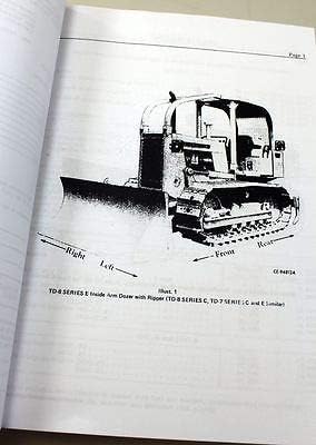
Figure 1: General layout of a TD-8 Series E Inside Arm Dozer, similar to the TD-7 Series E. This illustration helps in identifying the front, rear, right, and left sides of the machine for orientation during service procedures.
The manual is organized into major sections, each covering specific components or systems. Refer to the index for a complete list of topics.

Figure 2: Manual index page. This page outlines the main sections of the service manual, providing a quick reference to locate information on specific systems like the Electrical System, Engine, and Transmission.
Specifications
This section details the technical specifications for the IH Dresser TD-7 Series E TD-7E Crawler Dozer chassis. These specifications are essential for proper repair, part replacement, and ensuring the machine operates within design parameters.
- Manufacturer: Peaceful Creek
- Part Number: M-51332
- Material: Paper
- Item Package Quantity: 1
- ASIN: B07HS44RLM
- First Available: September 28, 2018
Preparation for Service (Setup)
Before commencing any service or repair work, ensure the dozer is safely positioned on a level surface, the engine is off, and the parking brake is engaged. Disconnect the battery to prevent accidental starting or electrical shorts. Use appropriate personal protective equipment (PPE) such as safety glasses, gloves, and steel-toed boots. Gather all necessary tools and replacement parts as specified for the particular repair task.
Electrical System
This section covers the wiring diagrams, component locations, and troubleshooting procedures for the dozer's electrical system. It includes details on the battery, starter, alternator, lighting, and various sensors and switches. Proper understanding of the electrical circuits is vital for diagnosing power issues, starting problems, and component malfunctions.

Figure 3: Electrical Wiring Diagram. This diagram illustrates the connections and components of the electrical system, including cables, switches, and relays, essential for diagnosing electrical faults.
Cooling System
Information regarding the radiator, water pump, thermostat, hoses, and cooling fan is provided here. This section outlines procedures for coolant replacement, leak detection, and component inspection to prevent engine overheating and ensure optimal operating temperatures.
Engine
This comprehensive section covers engine overhaul, repair, and adjustment procedures. It includes details on cylinder heads, pistons, crankshaft, camshaft, fuel system, and lubrication system. Specific torque specifications and assembly sequences are provided for critical engine components.
Hydraulic Torque Converter
This section details the inspection, disassembly, assembly, and testing of the hydraulic torque converter. It covers components such as the impeller, turbine, stator, and associated seals and bearings, crucial for power transmission.
Transmission (Gear Drive)
This section provides instructions for servicing the gear drive transmission, including removal, disassembly, inspection, repair, and reassembly of gears, shafts, bearings, and seals. Proper lubrication and adjustment procedures are also covered.
Transmission (Power Shift)
Detailed procedures for the power shift transmission are outlined, covering clutch packs, hydraulic control valves, and planetary gear sets. This includes troubleshooting hydraulic pressure issues, component replacement, and calibration.
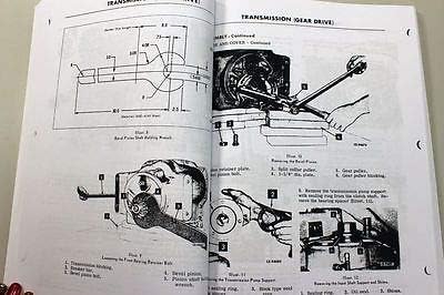
Figure 4: Transmission Component Diagrams. These illustrations show specialized tools and procedures for disassembling and assembling transmission components, such as removing the rear roller shaft and working with the transmission pump support.
Steering System
This section addresses the steering clutches, brakes, and control linkages. It provides instructions for adjustment, repair, and replacement of components to ensure precise and responsive steering control.
Sprocket Drive
Details on the final drive sprockets, chains, and associated bearings are covered here. Procedures for inspection, wear measurement, and replacement are provided to maintain efficient power transfer to the tracks.
Track and Track Frame Assembly
This section includes information on track links, pins, bushings, rollers, idlers, and track tensioning mechanisms. It outlines procedures for track removal, repair, and reinstallation, as well as track frame inspection and maintenance.
Equipment Hydraulic System
This section covers the hydraulic pump, control valves, cylinders, and associated hoses and fittings for the dozer blade and other attachments. It provides troubleshooting for hydraulic pressure issues, leak detection, and component repair or replacement.
Adjustments
This section compiles various adjustment procedures for different systems, including engine idle speed, valve clearances, brake settings, clutch engagement, and track tension. Accurate adjustments are critical for optimal performance and longevity of the dozer.
Gearmatic Winch Adapter
For dozers equipped with a Gearmatic winch, this section provides specific service and repair information for the winch adapter, including its mounting, power take-off (PTO) connections, and internal components.
Maintenance
While this is primarily a service manual, it includes guidelines for routine maintenance tasks that are often performed during service intervals. This includes fluid checks and changes (engine oil, hydraulic fluid, coolant), filter replacements, lubrication points, and general inspection procedures to prevent major breakdowns.
Troubleshooting
This section provides diagnostic charts and procedures to identify the root cause of common operational issues. It covers symptoms, possible causes, and recommended corrective actions for problems related to the engine, transmission, hydraulic system, electrical system, and steering. A systematic approach to troubleshooting can significantly reduce repair time.
Post-Service Testing (Operating)
After completing any repair or service, it is essential to perform functional tests to ensure the dozer operates correctly and safely. This includes checking fluid levels, verifying proper operation of controls, testing brakes and steering, and observing engine and transmission performance under light load conditions. Address any unusual noises, vibrations, or performance issues immediately.