1. Product Overview
This document provides instructions for the Walfront 5V - 24V Motor Forward/Reverse Controller Board. This device is designed to control the direction and timing of DC motors within a specified voltage range. It features programmable delay times and multiple trigger modes for versatile applications.
The controller board integrates a relay for motor control and a digital display for settings and status indication.
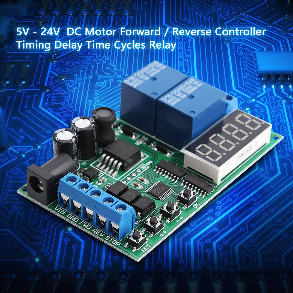
Figure 1: Angled view of the Walfront Motor Forward/Reverse Controller Board.
2. Features
- Constructed with a durable circuit board for extended operational life.
- Supports two input trigger modes: Low-Pulse trigger mode and Low-Level trigger mode.
- Includes three input control ports: Forward (FWD), Reverse (REV), and Stop (STOP).
- Dual power supply options: DC 6.5-25V or DC 5V (only one power supply should be connected at a time).
- Programmable delay times: 0.1-0.9 seconds, 1-9 seconds, and 1-9 minutes.
3. Specifications
| Parameter | Value |
|---|---|
| Power Supply | DC 6.5-25V or DC 5V |
| Working Current | 83mA |
| Standby Current | 41mA |
| Relay Load Current | <5A |
| Delay Time Ranges | 0.1-0.9 seconds, 1-9 seconds, 1-9 minutes |
| Dimensions | 8cm x 5cm (3.15 x 1.97 inches) |
| Weight | Approx. 51g (1.8oz) |
| Model Number | Walfrontnsrgqdi1xg |

Figure 2: Controller board showing approximate dimensions.
4. Component Identification
The controller board features various components for power input, motor control, and user interaction.

Figure 3: Front and back views of the controller board. The front shows the digital display, control buttons (SET, ++, OK), and terminal blocks. The back shows the 'MADE IN CHINA' marking and circuit traces.
Key Components:
- Digital Display: Shows current settings and status.
- Control Buttons (SET, ++, OK): Used for configuring operating modes and delay times.
- Power Input Terminals: For connecting the DC 6.5-25V or DC 5V working power supply. Labeled VIN, GND.
- Control Input Terminals: For FWD (Forward), REV (Reverse), and STOP signals.
- Motor Output Terminals: For connecting the motor power (M+, M-) and motor (P+, P-).
- Relays: Two blue relays are visible, responsible for switching motor direction.
5. Setup and Wiring
Proper wiring is essential for the safe and correct operation of the motor controller. Ensure all power is disconnected before making any connections.
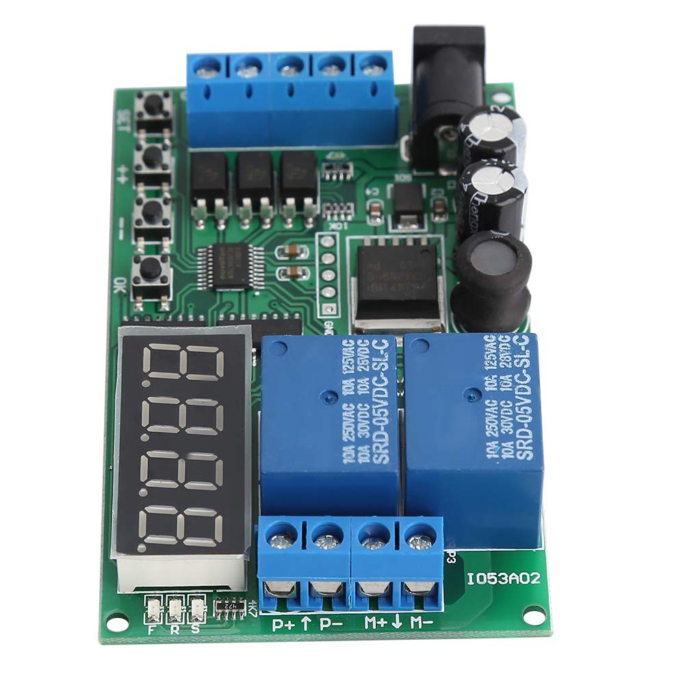
Figure 4: Wiring diagrams for the motor controller board, showing connections for working power and motor power.
- Working Power Supply Connection:
- Connect your DC 6.5-25V power supply to the VIN and GND terminals on the board.
- Alternatively, connect a DC 5V power supply to the dedicated 5V input terminals. Do not connect both power supplies simultaneously.
- Motor Power Supply Connection:
- Connect your motor's power source (DC 1-110V or AC 85-265V) to the P+ and P- terminals. Ensure correct polarity for DC.
- Motor Connection:
- Connect your DC motor to the M+ and M- terminals.
- Control Signal Connections (Optional):
- Connect external control signals to the FWD (Forward), REV (Reverse), and STOP terminals as required by your application. These inputs typically respond to low-pulse or low-level triggers.
Caution: Incorrect wiring can damage the board or connected components. Always double-check connections before applying power.
6. Operating Instructions
The controller offers various modes and programmable delay settings. The digital display shows the current mode or time value, and the SET, ++, and OK buttons are used for configuration.
6.1 Trigger Modes
The board supports two primary input trigger modes:
- Low-Pulse Trigger (Falling Edge): The controller reacts to a momentary transition from high to low voltage on the control input.
- Low-Level Trigger (Rising Edge): The controller reacts to a sustained low voltage level on the control input.
Refer to the product documentation or specific mode settings for how to select between these trigger types.
6.2 Control Ports
The three control ports allow for external command of motor direction and state:
- FWD (Forward): Activates the motor in the forward direction.
- REV (Reverse): Activates the motor in the reverse direction.
- STOP: Halts the motor operation.
6.3 Setting Delay Times
The controller allows for programming delay times in three ranges: 0.1-0.9 seconds, 1-9 seconds, and 1-9 minutes. The exact programming steps may vary depending on the specific firmware version. Generally, the process involves:
- Pressing the SET button to enter programming mode.
- Using the ++ button to adjust the time value or select a parameter.
- Pressing the OK button to confirm the selection or save the setting.
Consult the specific mode diagrams or a detailed programming guide for your module to understand the sequence for setting each parameter and delay range.
7. Maintenance
To ensure the longevity and reliable operation of your Walfront Motor Forward/Reverse Controller, follow these general maintenance guidelines:
- Cleaning: Keep the board clean and free from dust, dirt, and moisture. Use a soft, dry cloth to gently wipe the surface. Avoid using liquid cleaners or solvents.
- Storage: Store the controller in a dry, cool environment away from direct sunlight and extreme temperatures.
- Connections: Periodically check all wiring connections to ensure they are secure and free from corrosion. Loose connections can lead to intermittent operation or damage.
- Environmental Conditions: Operate the board within its specified temperature and humidity ranges to prevent damage.
8. Troubleshooting
If you encounter issues with your motor controller, consider the following troubleshooting steps:
- No Power/Display Off:
- Verify that the power supply is connected correctly to the VIN/GND or 5V terminals.
- Ensure the power supply voltage is within the specified range (DC 6.5-25V or DC 5V).
- Check for any loose wires or damaged power cables.
- Motor Not Responding:
- Confirm that the motor is correctly wired to the M+ and M- terminals.
- Check the motor's power supply connection (P+, P-) and ensure it is providing the correct voltage (DC 1-110V or AC 85-265V).
- Verify that the control signals (FWD, REV, STOP) are being applied correctly according to the selected trigger mode.
- Ensure the relay is clicking, indicating it is attempting to switch.
- Incorrect Motor Direction:
- Check the motor wiring to M+ and M-. Swapping these connections will reverse the motor's default direction.
- Ensure the FWD and REV control signals are being applied as intended.
- Timing Issues:
- Re-enter the programming mode and verify that the delay time settings are configured as desired.
- Ensure the correct time unit (seconds, minutes) is selected if applicable.
If problems persist after following these steps, contact customer support for further assistance.
9. Warranty and Support
Walfront products are designed for reliability and performance. For specific warranty information, please refer to the product packaging or the official Walfront website. In case of technical issues or questions not covered in this manual, please contact Walfront customer support through their official channels. When contacting support, please have your product model number (Walfrontnsrgqdi1xg) and purchase details ready.
