
1. Introduction
This manual provides essential information for the installation, operation, and maintenance of the SIEMENS LDU11.523A17 Gas Valve Proving System. This system is designed to ensure the safe and reliable operation of gas valves in industrial applications by verifying their leak-tightness before burner ignition, contributing to overall system safety and efficiency.
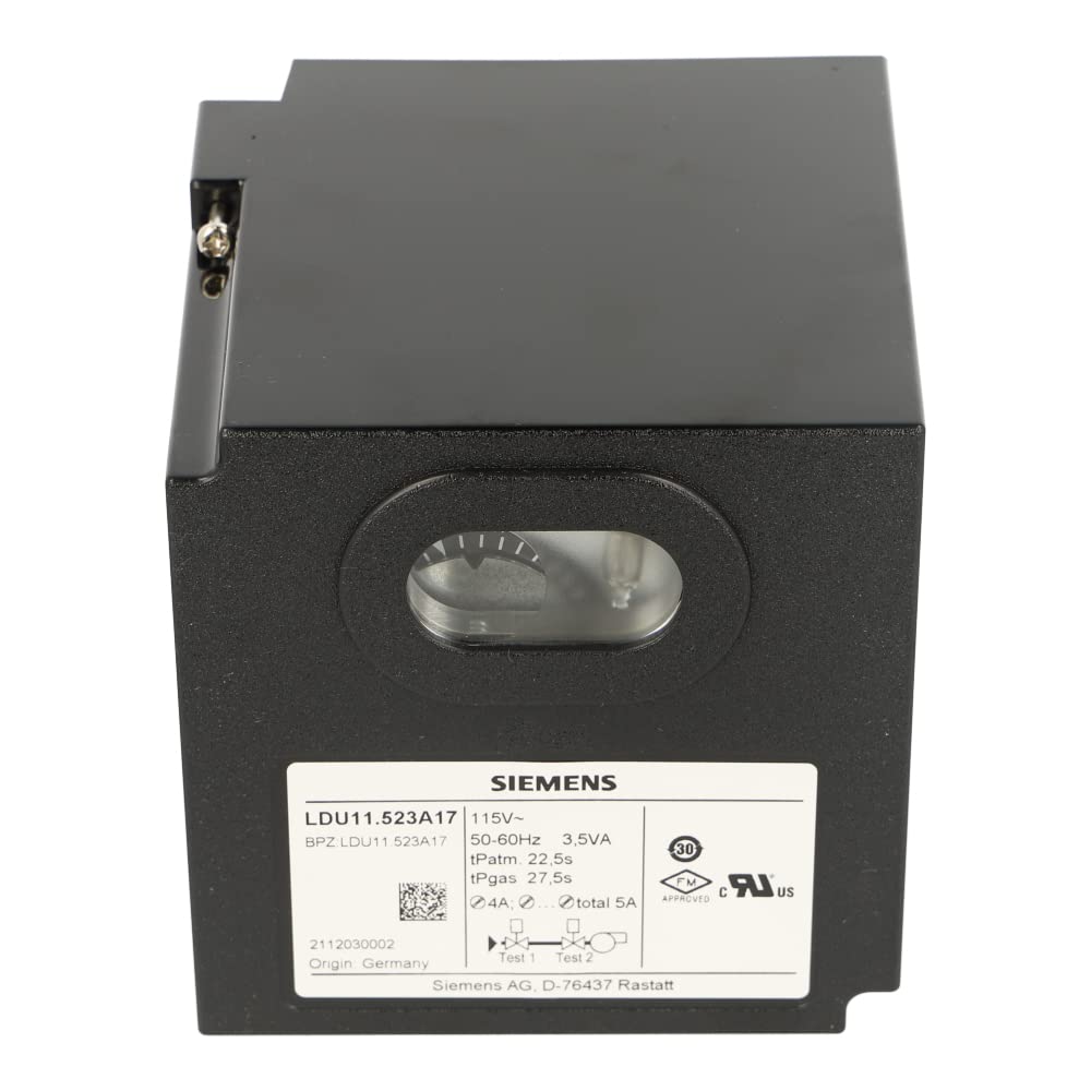
Front view of the SIEMENS LDU11.523A17 Gas Valve Proving System.
2. Safety Information
Adherence to the following safety precautions is crucial to prevent personal injury, equipment damage, and ensure proper system function.
- Always read and understand all instructions in this manual before attempting installation, operation, or maintenance.
- Installation, electrical connections, and maintenance procedures must be performed exclusively by qualified and authorized personnel.
- Ensure that all power supplies are disconnected and locked out before performing any service or maintenance on the unit.
- Verify proper grounding of the system to prevent electrical hazards.
- Comply with all applicable local, national, and international electrical and safety codes and regulations.
- Do not operate the system if any visible damage to the unit or its components is observed.

A universal safety warning symbol indicating important precautions.
3. Setup and Installation
Follow these guidelines for the correct setup and installation of the LDU11.523A17 system.
3.1. Mounting
Mount the unit securely in a clean, dry environment, protected from excessive vibration, direct heat sources, and corrosive atmospheres. Ensure sufficient clearance around the unit for proper ventilation and ease of wiring connections.
3.2. Wiring
Connect the power supply and control signals according to the provided wiring diagram. All electrical connections must conform to local electrical codes.
- Power Supply: AC100-110V, 50/60Hz.
- Input Signals: Connect the necessary control signals for valve proving, including T3 (pre-purge time) and T4 (proving time) inputs.
- Output Signals: Connect status indicators and alarm relays as required for system integration.

Detailed wiring diagram for the SIEMENS LDU11.523A17 Gas Valve Proving System, showing connections for power, inputs, and outputs.
4. Operating Instructions
This section details the operational procedures for the SIEMENS LDU11.523A17 Gas Valve Proving System.
4.1. Power On
Apply power to the unit (AC100-110V). The system will initiate a self-test sequence. Upon successful completion, the system will indicate readiness.
4.2. Proving Cycle
The LDU11.523A17 automatically initiates a gas valve proving cycle before allowing burner ignition. This cycle involves pressurizing the section of the gas valve being tested and monitoring for any pressure drops that would indicate a leak.
- T3 (Pre-purge time): Configured for 5 seconds. This is the initial time period for the system to prepare and establish stable conditions before the active leak detection phase.
- T4 (Proving time): Configured for 5 seconds. This is the duration during which the system actively monitors the gas valve for leaks. A successful proving cycle confirms the valve's integrity.
4.3. Status Indicators
Monitor the LED indicators on the unit for real-time system status:
- Green LED: Indicates the system is ready for operation or that the proving cycle was successful.
- Red LED: Indicates a fault condition, typically a gas leak detected during the proving cycle or a system error.

Close-up view of the LED status indicators on the SIEMENS LDU11.523A17 unit, showing green for ready and red for fault.
5. Maintenance
Regular maintenance is essential to ensure the continued optimal performance, reliability, and longevity of your LDU11.523A17 system.
5.1. Routine Checks
- Annual Inspection: Annually inspect all wiring and connections for signs of wear, damage, or loose terminals.
- Cleanliness: Keep the unit's exterior clean and free from dust, debris, and moisture. Do not use abrasive cleaners.
- Indicator Verification: Periodically verify that the LED status indicators are functioning correctly during system operation.
5.2. Calibration
Any calibration or internal adjustments should only be performed by authorized SIEMENS service personnel or certified technicians, strictly following manufacturer guidelines and using specialized equipment.

A technician performing a routine inspection on industrial control equipment, similar to the SIEMENS LDU11.523A17.
6. Troubleshooting
This section provides solutions for common issues encountered with the LDU11.523A17 Gas Valve Proving System. For problems not listed here, contact technical support.
| Problem | Possible Cause | Solution |
|---|---|---|
| Red LED active / Fault indication | Gas leak detected during proving cycle. | Inspect gas valves and associated piping for leaks. Rectify any leaks found. |
| Unit has no power | Power supply issue or incorrect voltage. | Verify the AC100-110V power supply is connected and active. Check fuses or circuit breakers. |
| System not initiating proving cycle | Incorrect or missing input signals (T3/T4). | Check the connections and functionality of the T3 and T4 input signals from the control system. |
| Intermittent faults | Loose wiring connections or environmental interference. | Tighten all terminal connections. Ensure proper grounding and shielding if electromagnetic interference is suspected. |

A visual representation of a troubleshooting flowchart, guiding users through common problems and solutions for industrial equipment.
7. Specifications
Key technical specifications for the SIEMENS LDU11.523A17 Gas Valve Proving System:
- Model: LDU11.523A17
- Brand: SIEMENS
- Power Supply: AC100-110V, 50/60Hz
- Pre-purge Time (T3): 5 seconds
- Proving Time (T4): 5 seconds
- Application: Gas Valve Proving System
- Manufacturer: Siemens
- ASIN: B07HCX7NP3
- Date First Available: July 17, 2019

Product label of the SIEMENS LDU11.523A17 Gas Valve Proving System, displaying model number, voltage, and other key specifications.
8. Warranty and Support
For detailed warranty information, technical assistance, or service inquiries regarding your SIEMENS LDU11.523A17 Gas Valve Proving System, please refer to the official SIEMENS website or contact their customer service department directly.
Manufacturer: Siemens
Contact: Refer to the official SIEMENS website for regional support contacts and service centers.
Online Resources: www.siemens.com

The official SIEMENS logo, representing the manufacturer of the gas valve proving system.