Introduction
This manual provides detailed instructions for the installation, operation, maintenance, and troubleshooting of the Walfront WS55-220 BLDC Motor Driver. Please read this manual thoroughly before using the product to ensure safe and efficient operation.
Safety Information
- Ensure all power is disconnected before installation or maintenance to prevent electric shock.
- Verify correct wiring connections according to the provided diagrams. Incorrect wiring can damage the device or connected components.
- Operate the driver within its specified voltage and current limits.
- Avoid exposing the device to moisture, extreme temperatures, or corrosive environments.
- Do not attempt to disassemble or modify the driver. Refer to qualified personnel for repairs.
Product Overview
The Walfront WS55-220 is a high-performance, cost-effective 3-phase BLDC motor controller. It is designed to drive BLDC motors efficiently, whether they are equipped with HALL sensors or not, making it suitable for a wide range of applications. This driver incorporates advanced technology to provide high speed, high torque, low noise, and low vibration operation.
Key features include:
- Versatile Motor Compatibility: Supports 3-phase BLDC motors, with or without HALL sensors.
- Comprehensive Protection: Includes overcurrent protection, overload protection, phase loss protection, and phase short circuit protection.
- Advanced Control: Offers alarm output and speed signal output functionalities.
- Broad Application: Suitable for various small equipment and power tools such as ventilation fans, grinding machines, and vibration motors in both domestic and industrial settings.

Figure 1: Walfront WS55-220 BLDC Motor Driver with indicated dimensions (9.5cm length, 3.5cm width, 6cm height).

Figure 2: The WS55-220 driver unit showing its heat sink, terminal blocks, and connected external potentiometer and toggle switch.
Specifications
| Parameter | Value |
|---|---|
| Model | WS55-220 |
| Brand | Walfront |
| Input Voltage | DC 20V-50V (Nominal 48V) |
| Maximum Power | 500W |
| Product Dimensions | 9.5 x 3.5 x 6 cm (3.74 x 1.37 x 2.36 inches) |
| Product Weight | 181 g (0.18 kg) |
| Protection Features | Overcurrent, Overload, Phase Loss, Phase Short Circuit |
| Speed Control Methods | External Potentiometer, External 10VDC Voltage |
| Rotation Direction | Forward/Reverse (via toggle switch) |
Setup and Installation
Proper installation is crucial for the safe and effective operation of the WS55-220 BLDC motor driver. Follow these steps carefully:
- Power Supply Connection: Connect the DC power supply to the "PWR" terminal block. Ensure the polarity is correct: '+' to positive, '-' to negative. The input voltage should be between 20V and 50V DC.
- Motor Connection: Connect the three phases of your BLDC motor to the 'U', 'V', and 'W' terminals on the "MOTOR" block.
- HALL Sensor Connection (Optional): If your motor has HALL sensors, connect them to the "HALL" terminal block. Match the 'HU', 'HV', 'HW' to the motor's HALL sensor outputs, and 'G' to ground, '+5V' to the 5V supply. If your motor does not have HALL sensors, these connections can be left open.
- Control Signal Connection:
- Speed Control:
- External Potentiometer: Connect the potentiometer to the 'S', 'A', and 'P' terminals on the "CONTROL" block. 'S' is the signal input, 'A' is the analog ground, and 'P' is the 10V power supply.
- External 10VDC Voltage: Connect an external 10VDC voltage source to the 'S' (signal input) and 'A' (analog ground) terminals.
- Forward/Reverse Control: Connect a toggle switch to the 'F' and 'R' terminals on the "CONTROL" block for direction control.
- Run/Stop Control: Connect a switch to the 'RUN' terminal and 'GND' for motor start/stop functionality.
- Alarm Output: The 'ALM' terminal provides an alarm output signal.
- Speed Signal Output: The 'SPD' terminal provides a speed signal output.
- Speed Control:
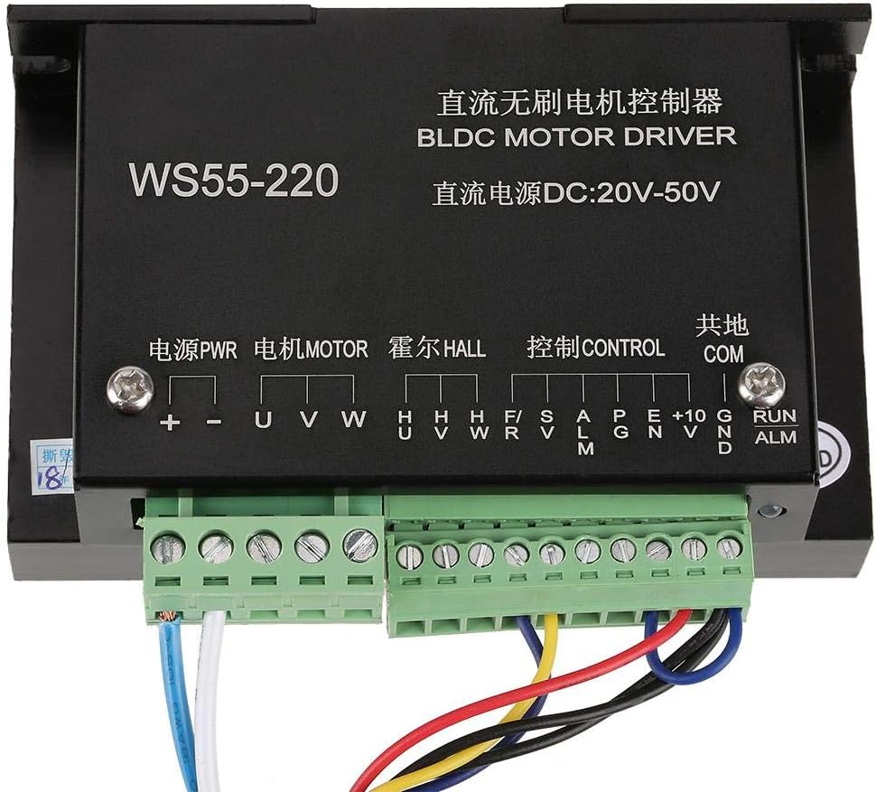
Figure 3: Detailed view of the terminal blocks on the WS55-220 driver, showing labels for Power, Motor, HALL, Control, and Common connections.

Figure 4: Example wiring diagram showing connections for power, motor, potentiometer for speed control, and a toggle switch for direction control.
Operating Instructions
Once the driver is correctly installed and wired, follow these steps for operation:
- Power On: Apply DC power to the driver. The status indicator (if present) should light up.
- Motor Start/Stop: Use the switch connected to the 'RUN' terminal to start or stop the motor.
- Speed Control:
- Using External Potentiometer: Rotate the knob of the connected potentiometer to adjust the motor speed. Turning it clockwise typically increases speed, and counter-clockwise decreases it.
- Using External 10VDC Voltage: Vary the input voltage (0-10VDC) to the 'S' terminal to control the motor speed.
- Direction Control: Utilize the toggle switch connected to the 'F' and 'R' terminals to change the motor's rotation direction (forward or reverse). Simply flip the switch to alternate directions.

Figure 5: Close-up of the external potentiometer (for speed adjustment) and the toggle switch (for forward/reverse control).
Maintenance
The Walfront WS55-220 BLDC motor driver is designed for reliable operation with minimal maintenance. However, periodic checks can help ensure its longevity and performance:
- Cleaning: Keep the driver free from dust and debris. Use a soft, dry cloth to clean the exterior. Do not use liquid cleaners.
- Ventilation: Ensure adequate airflow around the driver, especially around the heat sink, to prevent overheating. Do not obstruct ventilation openings.
- Connections: Periodically check all wiring connections to ensure they are secure and free from corrosion. Loose connections can lead to intermittent operation or damage.
- Environmental Conditions: Verify that the operating environment remains within the specified temperature and humidity ranges.
Troubleshooting
If you encounter issues with your Walfront WS55-220 BLDC motor driver, refer to the following troubleshooting guide:
| Problem | Possible Cause | Solution |
|---|---|---|
| Motor does not start. | No power supply; incorrect wiring; 'RUN' switch is off; motor or driver fault. | Check power connections and voltage. Verify all wiring. Ensure 'RUN' switch is engaged. Test motor independently if possible. |
| Motor runs erratically or with low power. | Incorrect motor phase connection; HALL sensor wiring issue (if used); insufficient power supply; overload. | Check motor phase connections (U, V, W). Verify HALL sensor wiring. Ensure power supply meets motor requirements. Reduce load. |
| Motor speed cannot be controlled. | Potentiometer or 10VDC input not connected correctly; faulty potentiometer/voltage source. | Check connections to 'S', 'A', 'P' terminals. Test the potentiometer or external voltage source. |
| Motor direction cannot be changed. | Direction toggle switch not connected correctly or faulty. | Verify connections to 'F' and 'R' terminals. Test the toggle switch. |
| Driver overheats. | Insufficient ventilation; excessive load on motor; ambient temperature too high. | Ensure proper airflow around the heat sink. Reduce motor load. Operate in a cooler environment. |
| Alarm output is active. | Overcurrent, overload, phase loss, or phase short circuit detected. | Identify and resolve the protection trigger (e.g., reduce load, check wiring for shorts). |
Warranty and Support
Walfront products are designed for quality and reliability. For warranty information or technical support, please refer to the retailer where you purchased the product or visit the official Walfront website. Please have your product model number (WS55-220) and purchase details ready when contacting support.


