1. Introduction
This manual provides detailed instructions for the installation, configuration, and operation of the Supermicro MBD-X11SCA-F-O motherboard. Designed for server and workstation applications, this motherboard supports Intel 8th/9th Generation Core i9/i7/i5/i3/Pentium/Celeron and Intel Xeon E Processors, offering robust performance and reliability. Please read this manual thoroughly before proceeding with installation.
2. Features
- Processor Support: Single Socket H4 (LGA 1151) for Intel 8th/9th Generation Core i9/i7/i5/i3/Pentium/Celeron and Intel Xeon E Processors (Coffee Lake-S), with CPU TDP support up to 95W.
- Chipset: Intel C246.
- Memory: DDR4 ECC/Non-ECC UDIMM, up to 64GB across 4 DIMM slots.
- Storage: 8x SATA3 (6Gbps) ports via Intel C246 controller, supporting RAID 0, 1, 5, 10.
- Expansion Slots: Multiple PCI-Express 3.0 slots for various expansion cards.
- Integrated Graphics: Onboard graphics with VGA output.
- Networking: Dual Gigabit Ethernet LAN ports.
- Management: Integrated Platform Management Interface (IPMI) for remote management.
- Form Factor: ATX.
3. Package Contents
Verify that all items are present and in good condition. If any items are damaged or missing, contact your vendor.
- Supermicro MBD-X11SCA-F-O Motherboard
- I/O Shield
- SATA Cables
- Quick Reference Guide
- Driver CD/DVD
4. Setup
4.1. Component Installation
Before installing any components, ensure the motherboard is placed on a non-conductive surface and you are grounded to prevent electrostatic discharge (ESD).
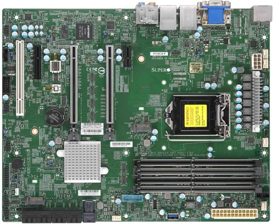
An overhead view of the Supermicro MBD-X11SCA-F-O motherboard, showcasing its various components including the CPU socket, RAM slots, PCIe slots, SATA ports, and I/O panel.
4.1.1. CPU Installation
- Open the CPU socket lever and lift the load plate.
- Carefully align the CPU with the socket, ensuring the gold triangle on the CPU matches the triangle on the socket. Do not force the CPU into the socket.
- Lower the load plate and secure it with the lever.
- Apply thermal paste to the CPU and install the CPU cooler according to its manufacturer's instructions.
4.1.2. Memory (RAM) Installation
- Open the clips on both ends of the DIMM slot.
- Align the notch on the DDR4 memory module with the key in the DIMM slot.
- Insert the module firmly until the clips snap into place. For optimal performance, install memory in matched pairs for dual-channel operation.
4.1.3. Storage Device Installation
- Connect SATA data cables from your storage drives (HDDs/SSDs) to the SATA ports on the motherboard.
- Ensure power cables are connected to your storage devices from the power supply.
4.1.4. Expansion Card Installation
- Locate an available PCI-Express slot.
- Remove the corresponding expansion slot cover from your chassis.
- Insert the expansion card firmly into the slot until it is seated correctly.
- Secure the card with a screw or retention clip.
4.2. Power Connections
- Connect the 24-pin ATX main power connector from your power supply to the corresponding header on the motherboard.
- Connect the 8-pin EPS/CPU power connector to the CPU power header.
4.3. Front Panel Connections
Connect the cables from your chassis's front panel (power button, reset button, HDD LED, power LED, USB ports, audio ports) to the corresponding headers on the motherboard. Refer to the motherboard's silkscreen labels for correct pin assignments.
5. Operating
5.1. Initial Boot and BIOS/UEFI Setup
- After assembling your system, connect a monitor, keyboard, and mouse.
- Power on the system. During POST (Power-On Self-Test), press the designated key (usually DEL or F2) to enter the BIOS/UEFI setup utility.
- Configure boot order, date/time, and other system settings as required. Save changes and exit.
5.2. Operating System Installation
Insert your operating system installation media (USB drive or DVD) and follow the on-screen prompts to install the operating system. After installation, install all necessary drivers from the provided driver CD or Supermicro's official website.
5.3. IPMI Remote Management
The MBD-X11SCA-F-O features Integrated Platform Management Interface (IPMI), allowing for remote monitoring and management of the system, even when the operating system is not running. Connect a dedicated LAN cable to the IPMI port and configure network settings via the BIOS/UEFI or IPMI web interface.
6. Maintenance
- Dust Removal: Regularly clean dust from the motherboard and components using compressed air to ensure proper airflow and prevent overheating.
- BIOS Updates: Periodically check the Supermicro website for BIOS/UEFI updates. Updates can improve stability, add support for new hardware, or fix bugs. Follow the provided instructions carefully when performing a BIOS update, often involving a USB drive.
- Connection Checks: Periodically verify that all cables (power, data, expansion cards) are securely connected.
7. Troubleshooting
7.1. No Power / No POST
- Ensure the power supply is connected correctly to the motherboard (24-pin ATX and 8-pin EPS).
- Verify the power supply is switched on and functioning.
- Check that the CPU is correctly seated and the CPU cooler is properly installed.
- Reseat RAM modules. Try booting with only one RAM module installed.
- Disconnect all non-essential peripherals and expansion cards to isolate the issue.
7.2. Operating System Not Booting
- Check the boot order in the BIOS/UEFI settings to ensure the correct drive is selected.
- Verify that the storage drive containing the operating system is properly connected and detected by the BIOS/UEFI.
- If recently installed, ensure all necessary drivers are loaded.
7.3. Component Not Detected
- For RAM, ensure modules are fully seated in their slots.
- For expansion cards, ensure they are correctly inserted into the PCIe slot and secured.
- For SATA devices, check both data and power cable connections.
- Consult the full motherboard manual for specific troubleshooting steps or beep codes.
8. Specifications
| Feature | Specification |
|---|---|
| Brand | Supermicro |
| Model Name | MBD-X11SCA-F-O |
| CPU Socket | LGA 1151 |
| Compatible Processors | Intel 8th/9th Gen Core i9/i7/i5/i3/Pentium/Celeron, Intel Xeon E Processors |
| Chipset | Intel C246 |
| RAM Memory Technology | DDR4 (ECC/Non-ECC UDIMM) |
| Max RAM Capacity | Up to 64GB |
| SATA Ports | 8x SATA3 (6Gbps) with RAID 0, 1, 5, 10 support |
| USB 2.0 Ports | 2 (additional USB 3.x ports available) |
| Integrated Graphics | Yes (VGA output) |
| Form Factor | ATX |
| Item Weight | 2.61 pounds |
| Product Dimensions | 14 x 13 x 3 inches (packaging) |
9. Warranty and Support
Supermicro products are covered by a manufacturer's warranty. For specific warranty terms and conditions, please refer to the warranty information included with your product or visit the official Supermicro website. For technical support, driver downloads, and further documentation, please visit the Supermicro support portal.
Supermicro Support: https://www.supermicro.com/support


