1. Introduction
This manual provides detailed instructions for the safe and effective use of your Proster Digital Multimeter. This high-precision, high-performance digital multimeter is designed to measure AC/DC voltage, current, resistance, capacitance, frequency, duty ratio, and temperature. It also features Non-Contact Voltage (NCV) detection, diode testing, transistor testing, and continuity checks. Its auto-ranging capability, True RMS function, and large backlit LCD display ensure ease of use and clear readings, making it suitable for laboratory, factory, and home applications.
2. Safety Information
To ensure safe operation and service of the meter, follow these instructions. Failure to observe these warnings can result in severe injury or death.
- Always ensure the meter is in the correct function and range before connecting test leads to the circuit.
- Do not apply more than the rated voltage, as marked on the meter, between the terminals or between any terminal and earth ground.
- Use caution when working with voltages above 30V AC RMS, 42V peak, or 60V DC. These voltages pose a shock hazard.
- Before measuring current, ensure the circuit is de-energized and the meter is connected in series with the load.
- Disconnect test leads from the circuit before changing functions or ranges.
- Replace the battery immediately when the low battery indicator appears to ensure accurate readings.
- Do not operate the meter if it appears damaged or if the test leads are damaged.
- Adhere to all local and national safety codes.
3. Product Overview
The Proster Digital Multimeter (Model PSTTL318) is a versatile tool for electrical measurements. It features a robust design with a large LCD display and intuitive controls.
3.1 Components and Accessories
The package includes the digital multimeter unit, a user's manual, a 9V battery, a pair of test probes, a temperature probe, and a pair of 10A small alligator clips.

3.2 Multimeter Features
- Auto-Ranging: Automatically selects the appropriate measurement range.
- True RMS: Provides accurate measurements for non-sinusoidal AC waveforms.
- NCV (Non-Contact Voltage): Detects AC voltage without physical contact.
- Data Hold: Freezes the displayed reading for easy recording.
- Backlight: Illuminates the LCD for visibility in low-light conditions.
- Diode Test: Checks the functionality of diodes.
- Transistor Test (hFE): Measures the DC current gain of transistors.
- Continuity Test: Indicates a continuous electrical path with an audible beep.
- Overload Protection: Ensures safety with 600V CAT IV and 1000V CAT III ratings, and double fuse protection.
- Low Battery Indication: Alerts when battery replacement is needed.
- Auto Power Off: Conserves battery life by automatically shutting down after a period of inactivity.
- Back Bracket: Allows the multimeter to stand upright for convenient viewing.
4. Setup
4.1 Battery Installation
- Ensure the multimeter is turned OFF.
- Locate the battery compartment cover on the back of the unit.
- Use a screwdriver to remove the screw securing the cover.
- Carefully remove the cover.
- Connect the 9V battery (included) to the battery clips, observing correct polarity.
- Place the battery into the compartment and replace the cover, securing it with the screw.
4.2 Connecting Test Leads
For most measurements, connect the black test lead to the 'COM' (common) jack and the red test lead to the 'VΩmA' jack. For high current measurements (up to 10A), connect the red test lead to the '10A' jack.

5. Operating Instructions
Turn the rotary switch to the desired function. The meter is auto-ranging, simplifying operation.
5.1 AC/DC Voltage Measurement
- Turn the rotary switch to the 'V~' for AC voltage or 'V=' for DC voltage.
- Connect the black test lead to the 'COM' jack and the red test lead to the 'VΩmA' jack.
- Touch the test probes to the circuit points where voltage is to be measured.
- Read the voltage value on the LCD display.
5.2 AC/DC Current Measurement
- Turn the rotary switch to 'mA~' or 'A~' for AC current, or 'mA=' or 'A=' for DC current.
- For currents up to 600mA, connect the red test lead to the 'VΩmA' jack. For currents up to 10A, connect the red test lead to the '10A' jack. The black lead remains in 'COM'.
- Important: De-energize the circuit and connect the meter in series with the load.
- Apply power to the circuit and read the current value.

5.3 Resistance Measurement
- Turn the rotary switch to 'Ω'.
- Connect the black test lead to 'COM' and the red test lead to 'VΩmA'.
- Ensure the circuit is de-energized before measuring resistance.
- Touch the test probes across the component to be measured.
- Read the resistance value on the LCD.

5.4 Capacitance, Frequency, and Duty Cycle Measurement
- Turn the rotary switch to the appropriate function (e.g., 'F' for capacitance, 'Hz%' for frequency/duty cycle).
- Connect the black test lead to 'COM' and the red test lead to 'VΩmA'.
- For capacitance, discharge the capacitor before measurement.
- Connect the probes to the component/circuit.
- Press the 'FUNC' button to cycle between capacitance, frequency, and duty cycle if they share a single rotary switch position.
5.5 Temperature Measurement
- Turn the rotary switch to '°C/°F'.
- Connect the temperature probe to the 'VΩmA' and 'COM' jacks, observing polarity.
- Place the tip of the temperature probe on or in the object whose temperature is to be measured.
- Read the temperature on the display. Press 'FUNC' to switch between Celsius and Fahrenheit.

5.6 Continuity Test
- Turn the rotary switch to the continuity symbol (often shared with diode/resistance).
- Connect the black test lead to 'COM' and the red test lead to 'VΩmA'.
- Touch the test probes to the two points of the circuit or component to be tested.
- If there is continuity (resistance below approximately 50Ω), the meter will emit an audible beep.

5.7 Diode Test
- Turn the rotary switch to the diode symbol (often shared with continuity/resistance).
- Connect the black test lead to 'COM' and the red test lead to 'VΩmA'.
- Touch the red probe to the anode and the black probe to the cathode of the diode. A forward voltage drop will be displayed.
- Reverse the probes. An open circuit ('OL') should be displayed for a good diode.
5.8 Transistor Test (hFE)
- Turn the rotary switch to the 'hFE' position.
- Identify the type of transistor (NPN or PNP) and its emitter, base, and collector leads.
- Insert the transistor leads into the corresponding sockets in the hFE test port.
- The hFE value (DC current gain) will be displayed on the LCD.
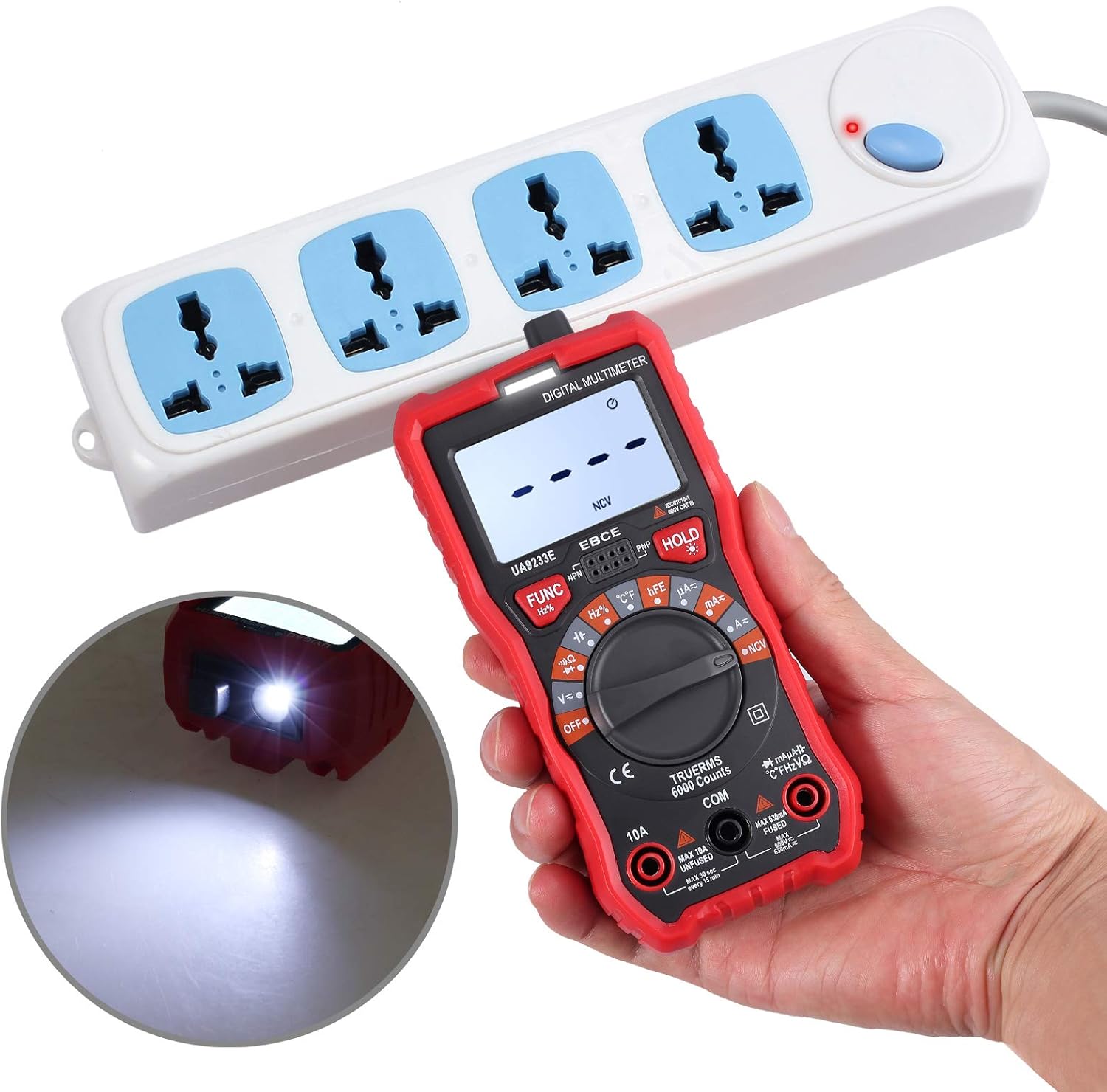
5.9 Non-Contact Voltage (NCV) Detection
- Turn the rotary switch to 'NCV'.
- Move the top end of the multimeter close to the conductor or outlet where AC voltage is suspected.
- The meter will emit an audible alarm and the NCV indicator light will flash if AC voltage is detected. The intensity of the alarm and flashing rate may increase with stronger fields.
5.10 Data Hold Function
Press the 'HOLD' button to freeze the current reading on the display. Press it again to release the hold and resume live readings.
5.11 Backlight Function
Press the backlight button (often integrated with 'HOLD' or a separate button with a light bulb icon) to turn the display backlight on or off. This improves visibility in dimly lit environments.
6. Maintenance
6.1 Cleaning
Wipe the meter with a damp cloth and mild detergent. Do not use abrasives or solvents. Keep the test leads clean and free of debris.
6.2 Battery Replacement
When the low battery indicator appears on the display, replace the 9V battery as described in Section 4.1. Using a low battery can lead to inaccurate readings.
6.3 Fuse Replacement
If the current measurement function stops working, the fuse may need replacement. Refer to the specifications for the correct fuse type and rating. Fuse replacement should only be performed by qualified personnel.
6.4 Storage
When not in use for extended periods, remove the battery to prevent leakage. Store the multimeter in a cool, dry place, away from direct sunlight and extreme temperatures.
7. Troubleshooting
- Meter does not turn on: Check battery installation and ensure the battery has sufficient charge. Replace if necessary.
- No reading or 'OL' displayed: Ensure test leads are correctly connected and making good contact with the circuit. Check if the function and range are appropriate for the measurement. 'OL' (Overload) indicates the measured value exceeds the selected range.
- Inaccurate readings: Replace the battery if the low battery indicator is on. Ensure test leads are not damaged. Verify the correct function and range are selected.
- Current measurement not working: Check the fuse. If blown, replace with the correct type and rating.
- NCV not detecting voltage: Ensure the NCV function is selected. The NCV sensor is located at the top of the meter; ensure it is close enough to the AC source.
8. Specifications
| Feature | Specification |
|---|---|
| Brand | Proster |
| Model Number | PSTTL318 |
| Display | 6000 Counts Digital LCD with Backlight |
| Power Source | 1 x 9V Battery (included) |
| Safety Rating | 600V CAT IV, 1000V CAT III |
| Dimensions (L x W x H) | 5.91 x 2.68 x 1.97 inches (148 x 67 x 48 mm) |
| Item Weight | 7.9 ounces (225 Grams) |
| Measurement Type | Multimeter |
| Battery Cell Type | Alkaline |
| Special Features | Auto Range, True RMS, NCV, Data Hold, Backlight, Diode Test, Triode Test, Continuity, Overload Protection, Low Battery Indication, Auto Power Off |

9. Warranty and Support
Proster products are designed for reliability and performance. For warranty information or technical support, please refer to the contact details provided with your purchase documentation or visit the official Proster website. Keep your purchase receipt as proof of purchase for warranty claims.


