
1. Introduction
The TRANE X13511528-01 BAYSENS077A is a 10K wired zone sensor designed for use with compatible HVAC control systems. This sensor accurately measures ambient temperature within a designated zone, providing essential data for maintaining optimal climate control. It is a passive device, requiring connection to a control panel or thermostat for operation. This manual provides detailed instructions for the safe installation, operation, and maintenance of the sensor.
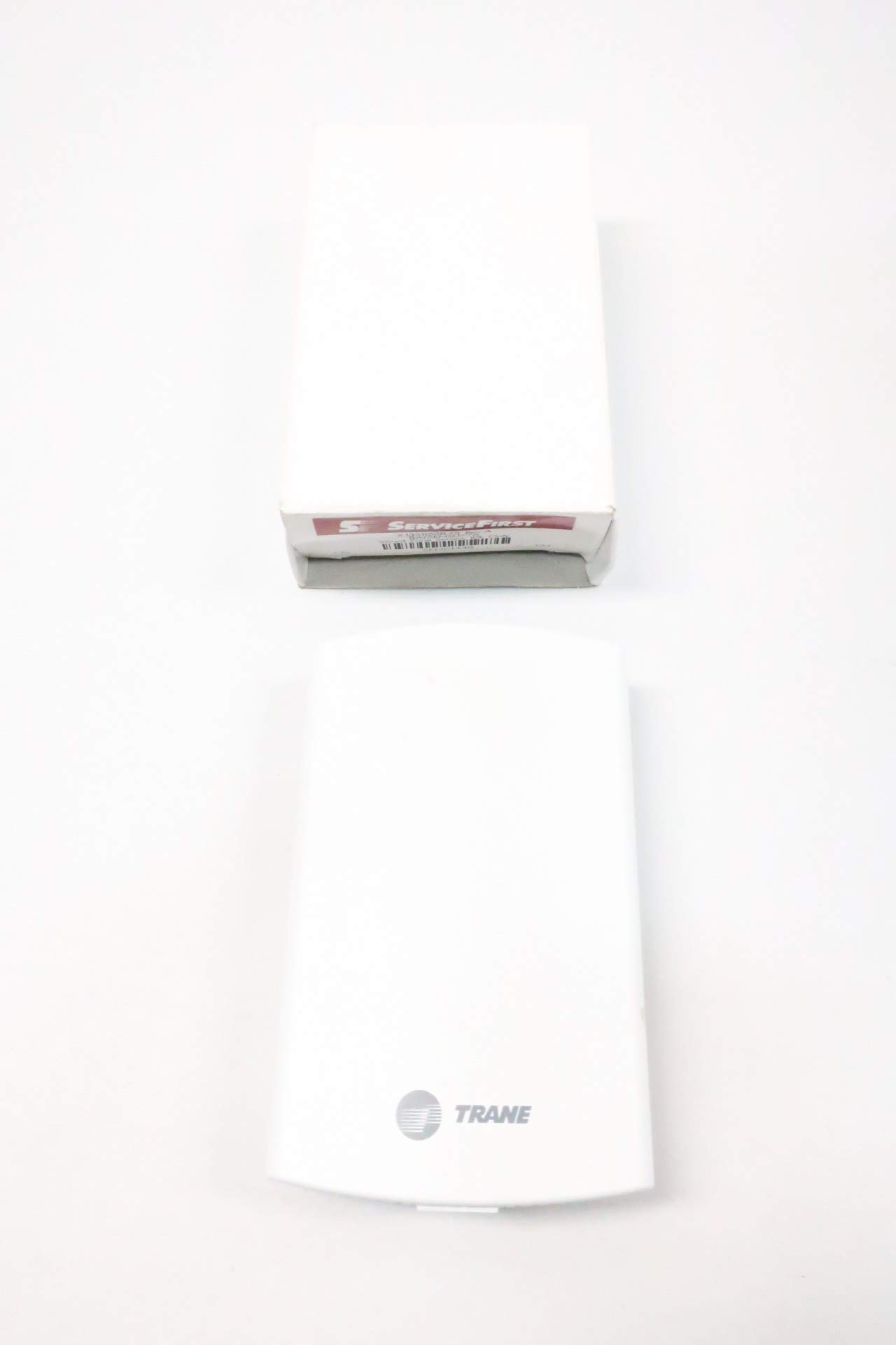
Figure 1: Front view of the TRANE X13511528-01 BAYSENS077A Wired Zone Sensor.
2. Safety Information
Please read and understand all safety instructions before installing or operating this device. Failure to follow these instructions may result in property damage, personal injury, or death.
- Electrical Hazard: Disconnect all power to the HVAC system before installing or servicing the sensor.
- Qualified Personnel: Installation and wiring should only be performed by qualified and experienced technicians.
- Proper Wiring: Ensure all wiring connections comply with local and national electrical codes.
- Environmental Conditions: Do not expose the sensor to moisture, extreme temperatures, or corrosive environments beyond its specified operating limits.
3. Package Contents
Verify that all items are present upon unpacking:
- TRANE X13511528-01 BAYSENS077A Wired Zone Sensor (1 unit)
- Mounting hardware (screws, anchors) - May vary by package.

Figure 2: Product packaging for the zone sensor.
4. Setup and Installation
4.1 Mounting Location
Select a suitable indoor location for the sensor that accurately represents the zone temperature. Avoid areas:
- Near heat sources (e.g., direct sunlight, lamps, appliances).
- Near cold sources (e.g., exterior walls, drafts from windows/doors).
- Behind doors or other obstructions that may block airflow.
- Where it may be exposed to vibration or excessive humidity.
Mount the sensor on an interior wall, typically 4-5 feet (1.2-1.5 meters) above the floor.
4.2 Mounting the Sensor
- Carefully separate the sensor cover from its back plate.
- Position the back plate on the chosen wall location.
- Mark the mounting holes.
- Drill pilot holes if necessary and insert wall anchors.
- Secure the back plate to the wall using the provided screws.
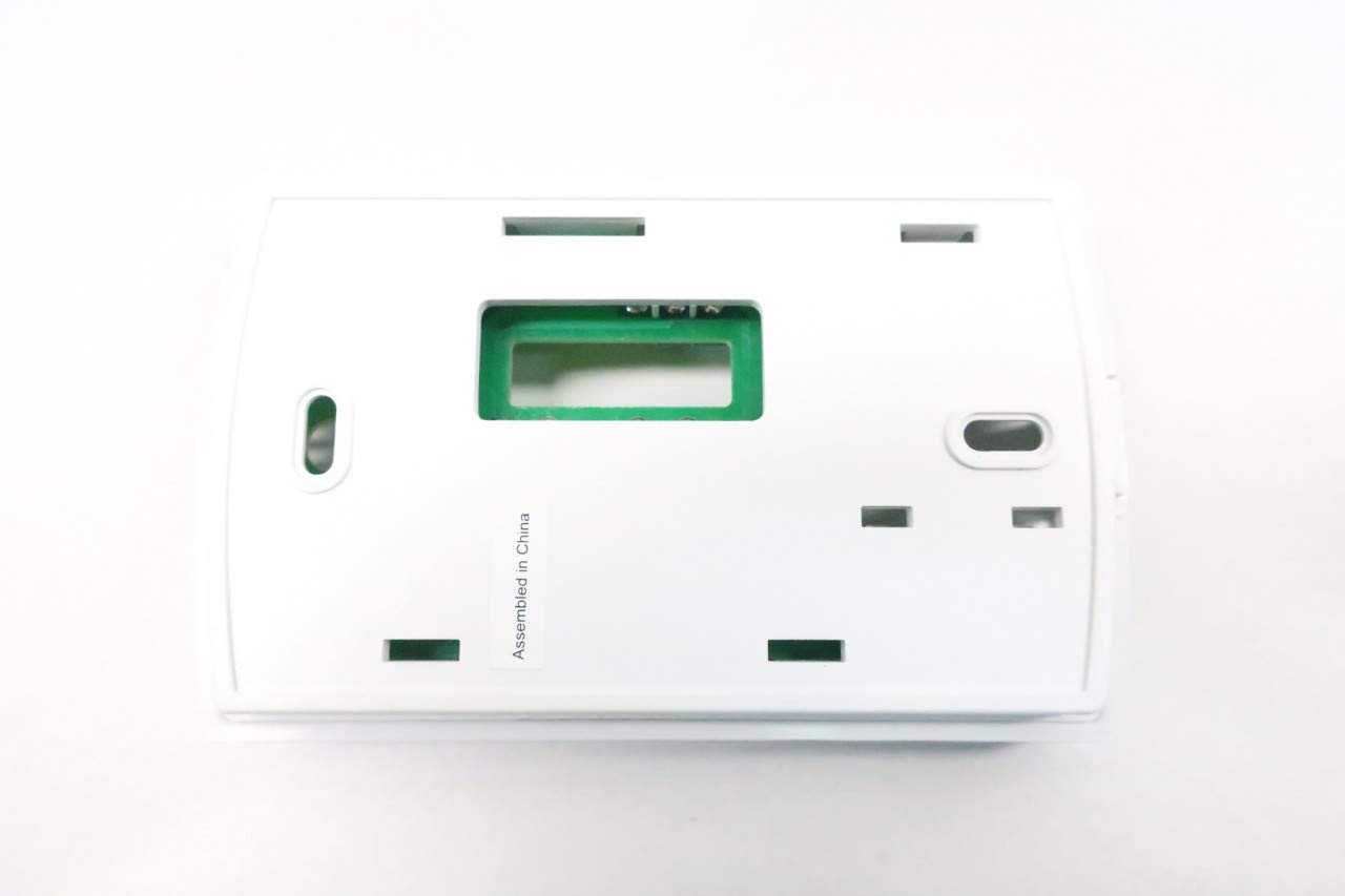
Figure 3: Back plate of the zone sensor, ready for mounting.
4.3 Wiring the Sensor
WARNING: Ensure all power to the HVAC system is disconnected before proceeding with wiring.
- Route the low-voltage wiring from the HVAC control panel/thermostat through the opening in the sensor's back plate.
- Connect the sensor wires to the appropriate terminals on the circuit board. Refer to the wiring diagram provided with your HVAC control system for specific terminal assignments. The sensor typically uses two wires for temperature sensing.
- Ensure connections are secure and wires are properly stripped (recommended strip length is often marked on the board).

Figure 4: Internal view of the sensor with circuit board and wiring terminals.

Figure 5: Close-up of the sensor's circuit board, highlighting wiring points and identification labels.
4.4 Final Assembly
Once wiring is complete, carefully reattach the sensor cover to the back plate, ensuring it snaps securely into place. Restore power to the HVAC system.
5. Operating Instructions
The TRANE X13511528-01 BAYSENS077A is a passive temperature sensor. It does not have user-adjustable settings or controls. Its operation is entirely dependent on the connected HVAC control panel or thermostat. The sensor provides a resistance value that changes with temperature, which the control system interprets to determine the ambient temperature of the zone.
- Ensure the connected control system is configured to recognize a 10K thermistor type sensor.
- Monitor the temperature readings on your control system to verify proper operation.
6. Maintenance
The TRANE X13511528-01 BAYSENS077A sensor requires minimal maintenance.
- Cleaning: Periodically wipe the exterior of the sensor with a soft, dry cloth to remove dust. Do not use abrasive cleaners or solvents.
- Inspection: Annually inspect the sensor for any visible damage or loose connections.
- Calibration: This sensor typically does not require field calibration. If temperature readings appear inaccurate, first check for proper placement and wiring before considering sensor replacement.
7. Troubleshooting
If you experience issues with your zone sensor, consider the following:
- No Temperature Reading:
- Check wiring connections at both the sensor and the control panel/thermostat.
- Ensure power is supplied to the HVAC control system.
- Verify the control system is configured for a 10K sensor.
- Inaccurate Temperature Reading:
- Review the sensor's mounting location for any heat or cold sources affecting its accuracy.
- Ensure the sensor is clean and free of dust buildup.
- Compare the sensor reading with a known accurate thermometer placed next to the sensor.
- Intermittent Readings:
- Inspect wiring for loose connections or damaged insulation.
- Check for electromagnetic interference from nearby electrical equipment.
If troubleshooting steps do not resolve the issue, contact a qualified HVAC technician for assistance.
8. Specifications
| Brand | TRANE |
| Model Number | X13511528-01 BAYSENS077A |
| Manufacturer Part Number | D633310-X13511528-01 BAYSENS077A |
| Revision | REV A |
| Type | Wired Zone Sensor (10K Thermistor) |
| Power Source | Corded Electric (Low Voltage) |
| Item Weight | 3.2 ounces |
| Battery Description | Battery not included |
| Unit Count | 1 Count |
| ASIN | B07GZWL5HY |
| ServiceFirst Part Number | SEN01448 |
9. Warranty and Support
For warranty information and technical support, please refer to the documentation provided with your TRANE HVAC system or contact TRANE customer service directly. Keep your purchase receipt for warranty claims.


