1. Introduction
This manual provides detailed instructions for the installation, operation, and maintenance of the KNACRO XY-TR01 Digital Temperature Humidity Control Module. This high-precision module is designed for automatic constant temperature and humidity control, featuring a digital display and dual relay outputs.

Figure 1: Front view of the KNACRO XY-TR01 module, showing the display, control buttons, and relay terminals.
2. Product Features
- High-precision digital display for temperature and humidity.
- Dual output for automatic constant temperature and humidity control.
- Utilizes an industrial-grade chip and high-precision SHT20 temperature and humidity sensor.
- Automatic Work Mode Identification: The system automatically identifies heating/cooling and humidification/dehumidification modes based on set start/stop values.
- Remote Parameter Setting: Parameters such as start/stop temperature/humidity and correction values can be set via UART communication.
- Real-time Data Reporting: When enabled, the module reports temperature, humidity, and relay status via UART at 1-second intervals.
- Temperature Correction Function (OFE): Allows adjustment of measured temperature from -10.0℃ to 10℃ to compensate for sensor bias.
3. Setup and Wiring
Careful wiring is essential for proper operation. Refer to the diagrams below for connection details.

Figure 2: Component layout and basic connections. This diagram shows the DC 6.0-30V power supply input, temperature relay output, humidity relay output, MicroUSB 5.0V power port, 1M temperature and humidity sensor probe connection, and control buttons (TM+, TM-, RH+, RH-).
3.1 Power Supply Connection
- Connect a DC 6.0-30V power supply to the V+ and V- terminals. Ensure correct polarity.
- Alternatively, the module can be powered via the MicroUSB 5.0V port.
3.2 Sensor Connection
- Connect the 1M temperature and humidity sensor probe to the designated header on the module.
3.3 Equipment Wiring
The module provides two relay outputs for controlling external heating/cooling and humidification/dehumidification equipment.
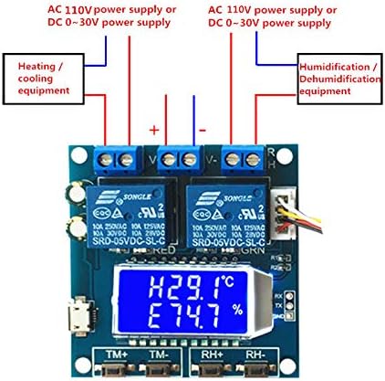
Figure 3: Wiring diagram for connecting heating/cooling equipment and humidification/dehumidification equipment. Both can be powered by AC 110V or DC 0-30V, connected through the respective relay terminals.
- Connect heating/cooling equipment to the temperature relay output terminals.
- Connect humidification/dehumidification equipment to the humidity relay output terminals.
- Ensure that the power supply for the controlled equipment matches its requirements (AC 110V or DC 0-30V).
4. Operating Instructions
4.1 Display Overview

Figure 4: The module's display showing current temperature (H25.8°C) and humidity (E54.9%). The "OUT" indicator signifies that a relay is currently active.
The module's display shows the current temperature and humidity. When a relay is active, the "OUT" indicator will appear on the interface.
4.2 Setting Start/Stop Temperature
- Press the TM+ or TM- button to enter temperature setting mode.
- Use TM+ and TM- to adjust the desired start and stop temperatures.
- The system automatically determines the operating mode:
- If Start Temperature > Stop Temperature: Cooling Mode (C). The relay activates when temperature ≥ Start Temperature and deactivates when temperature ≤ Stop Temperature.
- If Start Temperature < Stop Temperature: Heating Mode (H). The relay activates when temperature ≤ Start Temperature and deactivates when temperature ≥ Start Temperature.
4.3 Setting Start/Stop Humidity
- Press the RH+ or RH- button to enter humidity setting mode.
- Use RH+ and RH- to adjust the desired start and stop humidities.
- The system automatically determines the operating mode:
- If Start Humidity > Stop Humidity: Dehumidification Mode (D). The relay activates when humidity ≥ Start Humidity and deactivates when humidity ≤ Stop Humidity.
- If Start Humidity < Stop Humidity: Humidification Mode (E). The relay activates when humidity ≤ Start Humidity and deactivates when humidity ≥ Stop Humidity.
4.4 Temperature/Humidity Correction (OFE)
To correct potential sensor bias:
- Access the correction setting (specific button combination or UART command, refer to advanced documentation if available).
- Adjust the correction value within the range of -10.0 to 10.0. The actual temperature/humidity will be (measured value + correction value).
4.5 UART Communication
The module supports UART communication for remote parameter setting and real-time data reporting. Refer to the technical specifications or advanced user guide for detailed UART protocol information.
5. Maintenance
- Keep the module clean and free from dust and moisture.
- Ensure proper ventilation around the module to prevent overheating.
- Regularly check wiring connections for security and integrity.
- Avoid exposing the module to extreme temperatures or corrosive environments.
6. Troubleshooting
| Problem | Possible Cause | Solution |
|---|---|---|
| Module does not power on. | Incorrect power supply voltage or polarity; loose connection. | Verify power supply (DC 6.0-30V or MicroUSB 5.0V) and connections. Check polarity. |
| Relay not activating. | Set temperature/humidity not reached; relay disabled; wiring issue. | Check set start/stop values. Ensure relay enabling is active (default). Verify equipment wiring. |
| Inaccurate temperature/humidity readings. | Sensor not properly connected; sensor fault; environmental interference. | Check sensor connection. Apply temperature/humidity correction (OFE function). Ensure sensor is in a stable environment. |
| "OUT" indicator not appearing when expected. | Relay not activated; display fault. | Confirm operating conditions meet relay activation criteria. Check relay functionality. |
7. Specifications
| Model Number | XY-TR01 |
| Input Voltage | DC 6.0-30V (via terminal) or MicroUSB 5.0V |
| Temperature Range | -20℃ to 60℃ |
| Humidity Range | Not explicitly stated in provided data, but implied by product function. |
| Relay Output Current | 10A (at 250VAC, 125VAC, 30VDC, 28VDC) |
| Sensor | High-precision SHT20 temperature and humidity sensor |
| Dimensions | Approx. 57mm x 60mm |
| Item Weight | 2.82 ounces (0.08 Kilograms) |
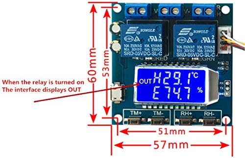
Figure 5: Physical dimensions of the KNACRO XY-TR01 module, showing approximate measurements of 57mm width and 60mm length.
8. Warranty and Support
For warranty information or technical support, please contact your retailer or the manufacturer, KNACRO. Refer to the product packaging or purchase documentation for specific contact details.
Note: The product is sold by KNACRO and fulfilled by Amazon. Return policy is 30 days.


