1. Introduction
The EUCHNER ESM-BA301 is a safety relay designed for monitoring safety functions in industrial applications. This device features 3 normally open (NO) and 1 normally closed (NC) output, utilizing screw terminals for secure connections. It is engineered for DIN-rail mounting, optimizing space and cable management within electrical enclosures, load centers, and equipment cabinet racks. This manual provides essential information for the safe and effective installation, operation, and maintenance of your ESM-BA301 safety relay.
2. Safety Instructions
Always adhere to local and national electrical codes and regulations. Installation, wiring, and maintenance should only be performed by qualified personnel. Disconnect all power before working on the device or its connections. Ensure proper grounding. Failure to follow these instructions may result in serious injury or damage to equipment.
- Power Disconnection: Always ensure power is disconnected before installation or maintenance.
- Qualified Personnel: Only trained and qualified electricians should install and service this device.
- Environmental Conditions: Operate the relay within specified environmental conditions (temperature, humidity).
- Proper Wiring: Use appropriate wire gauges and ensure all connections are secure and correct.
3. Setup and Installation
The ESM-BA301 safety relay is designed for easy mounting on standard DIN-rails. Follow these steps for proper installation and wiring.
3.1 DIN-Rail Mounting
Locate an appropriate section of a 35mm DIN-rail within your electrical enclosure. Align the relay's mounting clip with the DIN-rail and press firmly until it clicks into place. Ensure the relay is securely fastened and does not wobble.
3.2 Wiring Connections
Refer to the diagram on the relay and the image below for terminal identification. Use appropriate insulated wires for all connections. Tighten all screw terminals securely to prevent loose connections and potential hazards.
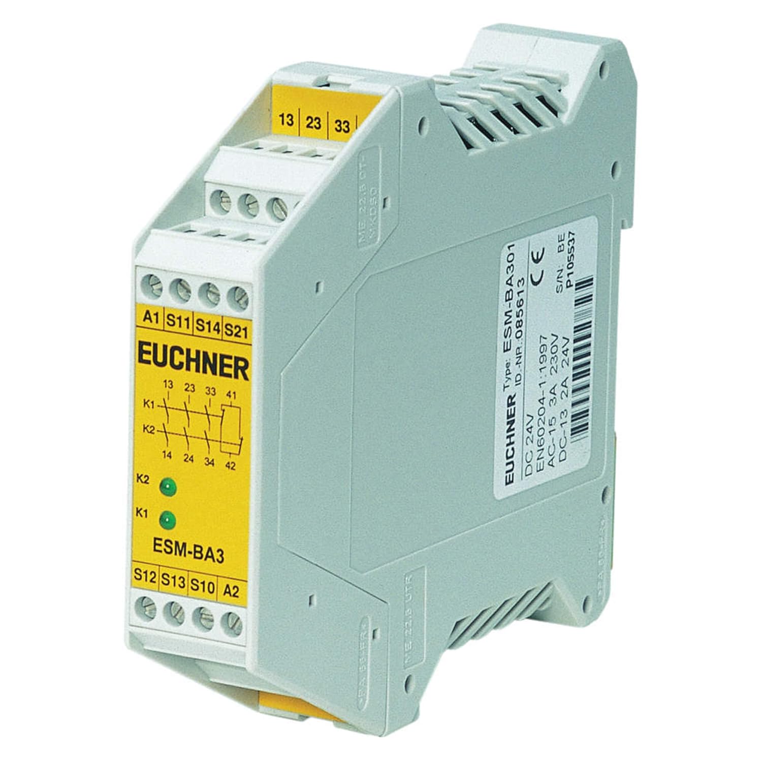
Figure 1: Front view of the EUCHNER ESM-BA301 Safety Relay. The image displays the yellow front panel with various screw terminals and their corresponding labels. Key terminals visible include A1, S11, S14, S21 for inputs, and S12, S13, S10, A2 at the bottom. Output terminals 13, 23, 33, and 41 are located at the top. Two green LED indicators, K1 and K2, are also visible, indicating the status of the internal relays. The side of the unit shows product information such as 'Type: ESM-BA301', 'ID.-NR. 085613', 'DC 24V', 'AC-15 3A 230V', and 'DC-13 2A 24V', along with the CE mark and serial number.
Terminal Designations:
- A1, A2: Power Supply (AC/DC 24V)
- S11, S12, S13, S14, S21, S10: Input terminals for safety circuits (e.g., emergency stop buttons, safety gates). Refer to the specific application wiring diagram for correct connections.
- 13, 23, 33: Normally Open (NO) Safety Outputs (3 NO)
- 41: Normally Closed (NC) Auxiliary Output (1 NC)
Ensure that the power supply voltage matches the relay's specifications (AC/DC 24V). Connect safety devices to the appropriate input terminals as per your system's safety circuit design.
4. Operating Principles
The ESM-BA301 safety relay monitors the status of connected safety devices. When the safety circuit is closed and all conditions are met, the internal relays (K1, K2) will energize, closing the normally open safety outputs (13, 23, 33) and opening the normally closed auxiliary output (41).
4.1 LED Indicators
- K1 (Green LED): Indicates the status of the first internal relay. Lit when K1 is energized.
- K2 (Green LED): Indicates the status of the second internal relay. Lit when K2 is energized.
Both K1 and K2 LEDs must be lit for the safety outputs to be closed, indicating a safe operating state. If either LED is off, it indicates a fault or an open safety circuit.
5. Maintenance
The EUCHNER ESM-BA301 safety relay is designed for long-term, maintenance-free operation under normal industrial conditions. Regular inspection of wiring connections for tightness and signs of damage is recommended. Keep the unit free from excessive dust and moisture. Do not attempt to open or repair the unit; refer to qualified service personnel for any issues beyond basic troubleshooting.
6. Troubleshooting
If the ESM-BA301 is not functioning as expected, perform the following checks:
- No Power/LEDs Off:
- Verify that the power supply (A1, A2) is correctly connected and providing the specified AC/DC 24V.
- Check for blown fuses or tripped circuit breakers in the power supply line.
- K1 or K2 LED Off (Safety Outputs Not Activating):
- Inspect all safety input connections (S11, S12, S13, S14, S21, S10) for proper wiring and continuity.
- Ensure all connected safety devices (e.g., emergency stop buttons, safety gates) are in their safe, closed state.
- Check for any short circuits or open circuits in the safety loop.
- Incorrect Output State:
- Verify that the load connected to the output terminals (13, 23, 33, 41) is within the specified current and voltage ratings.
- Ensure the safety circuit is correctly reset after a fault condition.
If the problem persists after performing these checks, contact EUCHNER technical support or a qualified service technician.
7. Specifications
Detailed technical specifications for the EUCHNER ESM-BA301 Safety Relay:
| Attribute | Value |
|---|---|
| Model Number | ESM-BA301 |
| Manufacturer | Euchner |
| Output Configuration | 3 NO (Normally Open) + 1 NC (Normally Closed) |
| Terminal Type | Screw TERMINALS |
| Category | Category 4 (Non-TIME-Delayed) |
| Supply Voltage | AC/DC 24 V |
| Current Rating (AC-15) | 3 Amps @ 230V |
| Current Rating (DC-13) | 2 Amps @ 24V |
| Mounting Type | DIN Rail Mount |
| Number Of Poles | 4 |
| Package Dimensions | 5.12 x 3.94 x 3.94 inches; 5.6 ounces |
| Date First Available | August 16, 2018 |
8. Warranty and Support
For specific warranty information, please refer to the documentation provided with your purchase or contact EUCHNER directly. Technical support is available through EUCHNER's official channels. When contacting support, please have your model number (ESM-BA301) and serial number (found on the side label of the unit) ready.
For further assistance, visit the official EUCHNER website or consult your local distributor.


