1. Introduction
This manual provides essential information for the proper setup, operation, and maintenance of your Tektronix TBS1052B-EDU Digital Oscilloscope. Designed for educational environments and general-purpose applications, this instrument offers reliable performance for waveform visualization and measurement.
2. Setup
2.1 Unpacking and Inspection
Carefully remove the oscilloscope from its packaging. Inspect the instrument for any signs of damage that may have occurred during transit. Retain the packaging materials for future transport or storage.
2.2 Power Connection
Connect the provided power cord to the AC power inlet on the rear panel of the oscilloscope. Ensure the power source matches the voltage requirements specified on the instrument's label. The power inlet is located on the right side of the rear panel when viewed from the back.

Figure 2.1: Rear view of the TBS1052B-EDU oscilloscope, highlighting the power input and connectivity ports.
2.3 Probe Connection
Connect the oscilloscope probes to the BNC input connectors on the front panel. The TBS1052B-EDU features two input channels, Channel 1 (yellow) and Channel 2 (blue). Ensure probes are properly compensated for accurate measurements.
2.4 Initial Power On
Press the power button located on the front panel to turn on the oscilloscope. The instrument will perform a self-test and display the startup screen. Allow a few moments for the system to initialize.
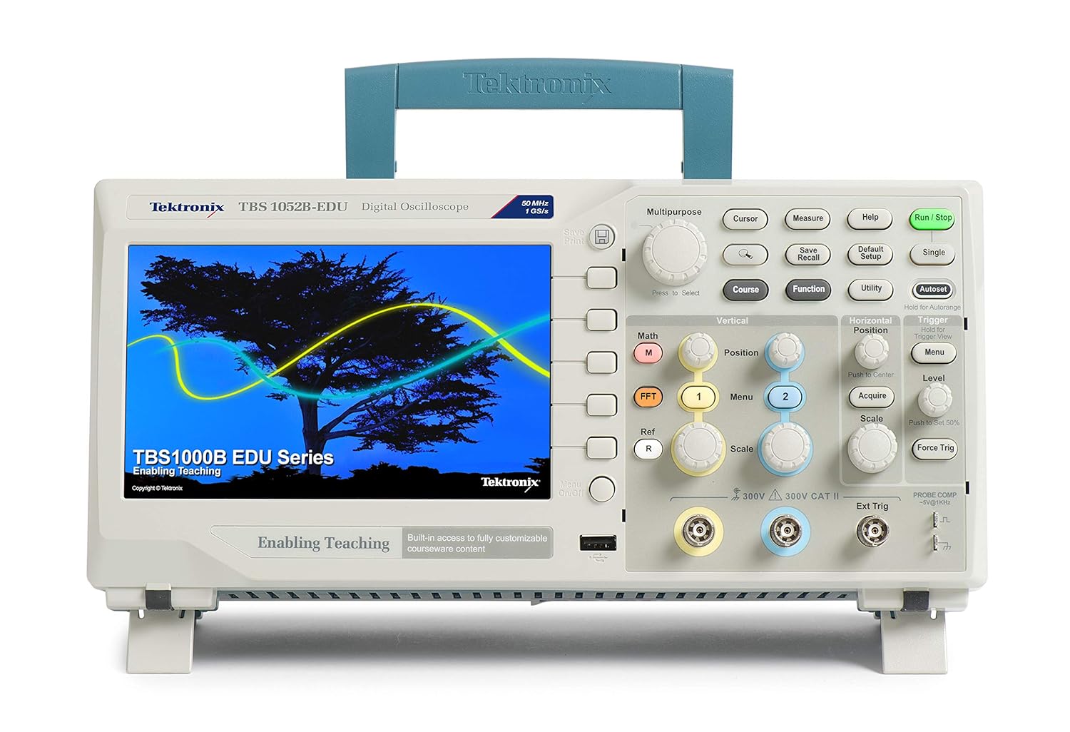
Figure 2.2: Front view of the TBS1052B-EDU oscilloscope, showing the display and main controls.
3. Operating Instructions
3.1 Front Panel Controls Overview
The front panel of the TBS1052B-EDU is intuitively designed for ease of use. It is divided into several functional areas: Display, Vertical Controls, Horizontal Controls, Trigger Controls, and Multipurpose/Measurement Controls.
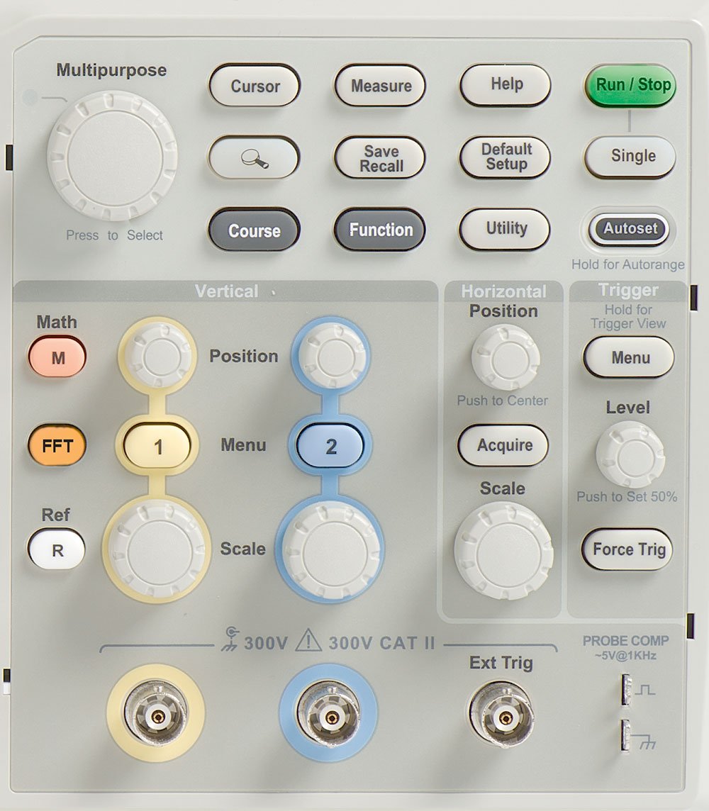
Figure 3.1: Detailed view of the oscilloscope's control panel, illustrating the layout of knobs and buttons for various functions.
3.2 Basic Waveform Display
To display a waveform:
- Connect a signal source to Channel 1 or Channel 2.
- Press the Autoset button. The oscilloscope will automatically adjust vertical, horizontal, and trigger settings to display a stable waveform.
- Adjust the Vertical Scale (Volts/Div) and Horizontal Scale (Sec/Div) knobs to fine-tune the waveform's appearance.

Figure 3.2: The oscilloscope displaying a typical square waveform, demonstrating its measurement capabilities.
3.3 Triggering
The trigger system stabilizes repetitive waveforms and captures single-shot events. Use the Trigger Level knob to set the voltage level at which the trigger occurs. The Trigger Menu button provides access to advanced trigger settings like Edge, Pulse Width, and Video triggers.
3.4 Measurements and Analysis
The TBS1052B-EDU offers various measurement tools:
- Automatic Measurements: Press the Measure button to display a menu of common measurements such as Frequency, Period, Peak-to-Peak Voltage, and RMS.
- Cursors: Use the Cursor button to activate voltage and time cursors for precise manual measurements.
- Math Functions: The Math button allows for waveform operations like addition, subtraction, multiplication, and Fast Fourier Transform (FFT) for frequency domain analysis.
3.5 Saving and Recalling Settings
The Save/Recall button allows you to save instrument setups and waveforms to internal memory or a USB flash drive. This feature is useful for repeating specific tests or analyzing captured data offline.
4. Maintenance
4.1 Cleaning the Instrument
To clean the exterior of the oscilloscope, use a soft cloth dampened with a mild detergent solution. Do not use abrasive cleaners or solvents that could damage the plastic casing or display. Ensure the instrument is powered off and unplugged before cleaning.
4.2 Storage
When not in use for extended periods, store the oscilloscope in a dry, dust-free environment, preferably in its original packaging. Avoid extreme temperatures and humidity.
4.3 Calibration
For optimal performance, periodic calibration by qualified service personnel is recommended. Refer to the official Tektronix website or contact customer support for calibration services.
5. Troubleshooting
This section provides solutions to common issues you might encounter with your TBS1052B-EDU oscilloscope.
| Problem | Possible Cause | Solution |
|---|---|---|
| No waveform displayed | No input signal; incorrect vertical/horizontal settings; trigger not set correctly. | Verify signal connection; press Autoset; adjust Vertical Scale, Horizontal Scale, and Trigger Level. |
| Unstable waveform | Trigger level or source incorrect; signal noise. | Adjust Trigger Level; ensure trigger source matches input channel; use averaging if available. |
| Incorrect measurements | Probe compensation incorrect; wrong measurement type selected. | Compensate probes; select appropriate measurement from the Measure menu. |
| Instrument does not power on | Power cord not connected; power outlet issue. | Check power cord connection; test power outlet with another device. |
6. Specifications
The Tektronix TBS1052B-EDU Digital Oscilloscope features the following key specifications:
- Model Number: TBS1052B-EDU
- Bandwidth: 50 MHz
- Channels: 2
- Sample Rate: 1 GS/s (Real-time)
- Dimensions (Package): 43.43 x 31.5 x 21.08 cm (17.1 x 12.4 x 8.3 inches)
- Weight (Package): 3.04 kg (6.7 lbs)
- Manufacturer: Tektronix
7. Warranty Information
The Tektronix TBS1052B-EDU Digital Oscilloscope comes with a 5-year Tektronix warranty. This warranty covers defects in materials and workmanship under normal use. For detailed terms and conditions, please refer to the warranty documentation included with your product or visit the official Tektronix website.
8. Support
For technical assistance, product inquiries, or service requests, please contact Tektronix customer support. You can find contact information and additional resources on the official Tektronix website. Please have your model number (TBS1052B-EDU) and serial number ready when contacting support.
For more information, visit: www.tek.com


