1. Introduction
This Walfront VFD Drive Inverter (Model AT1-4000X) is designed to convert 220V AC single-phase power to 3-phase power, enabling precise speed control for 3-phase motors. It utilizes a unique control method for excellent performance, featuring high torque and a wide speed regulating range. The inverter offers good anti-trip performance and adaptability to varying power conditions, minimizing interference from temperature, humidity, and dust.
Key features include PWM control and electromagnetic compatibility, ensuring stable and reliable operation. It is designed for easy operation and installation, with intuitive buttons for quick adjustments like fast start and stop response, and high torque at low speeds.
2. Safety Information
WARNING: Risk of electric shock. Read this manual thoroughly before installation and operation. Always wait at least 5 minutes for capacitor discharge after disconnecting the power supply before handling the unit. Ensure all wiring is performed with the power off and appropriate personal protective equipment (PPE) is worn.

Figure 2.1: Front view of the Walfront VFD Drive Inverter, showing the control panel and safety warning label.
3. Product Overview
3.1. Models and Appearance

Figure 3.1: Comparison of new and old models of the Walfront VFD Drive Inverter. Both models offer similar functionality.
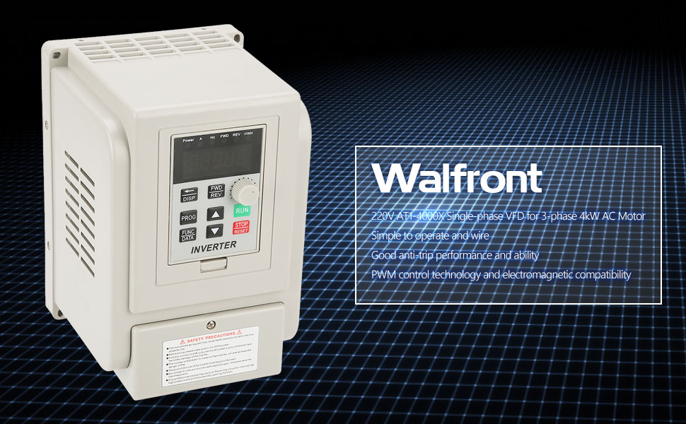
Figure 3.2: The VFD Drive Inverter features a beautiful appearance with high-quality protective paint, making it resistant to rust and providing strong compressive ability. Its ergonomic design ensures convenient and fast use.
3.2. Control Panel

Figure 3.3: Detailed view of the control panel. It features a 5-digit LED display, DISP button, PROG button, FUNC/DATA button, FWD/REV buttons, Up/Down buttons, RUN button, and STOP/RESET button. Function indicator lights show CW (FWD), CCW (REV), speed (r/min), frequency (H), voltage (V), and current (A).
3.3. Cooling System
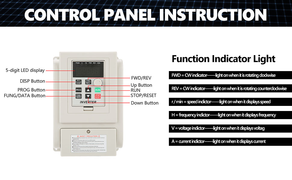
Figure 3.4: The inverter incorporates double-row fan ports for enhanced heat dissipation, in addition to traditional ventilation holes. Horizontal exhaust holes on the side prevent heat accumulation.
4. Setup and Wiring
Before proceeding with any wiring, ensure the VFD is disconnected from the power supply. Always wear appropriate personal protective equipment (PPE) to prevent electric shock.
4.1. Wiring Diagram

Figure 4.1: General wiring diagram for the VFD Drive Inverter. This diagram illustrates connections for a 220V single-phase power supply, a 3-phase motor, and external control inputs.
4.2. Wiring Procedure
- Connect Power Wires: Tie the 220V single-phase power supply wires to the L1 and L2 terminals on the VFD.
- Connect Motor Wires: Connect the three motor wires to the U, V, and W terminals on the VFD.
- Verify Connections: After wiring, ensure that all power and motor wires are securely tied under their respective terminals.
- Braking Resistor (Optional): This VFD supports connecting a braking resistor (not included) to the DC+ and DB terminals. A braking resistor helps dissipate energy generated by the motor during deceleration, which is useful for high-torque equipment or applications requiring fast braking, such as engraving machine spindles (e.g., stopping a 24,000 rpm spindle within 0.5s-2s).
4.3. Wiring Demonstration Video
Video 4.1: This video demonstrates the step-by-step process of wiring the VFD Drive Inverter to a 220V single-phase power supply and a 3-phase motor. It also shows how to reverse motor direction by exchanging output terminals.
5. Operating Instructions
After successful wiring and ensuring all safety precautions are met, you can proceed with operating the VFD.
5.1. Initial Power-Up and Frequency Check
- Power on the VFD.
- Turn the frequency adjustment knob clockwise fully. The panel should display 50 Hz.
- Verify that the motor's rated frequency matches the inverter's rated frequency. For example, if the motor's rated frequency is 50 Hz, ensure the VFD is set accordingly.
5.2. Adjusting Acceleration and Deceleration Times
If your motor drives high-torque equipment, it is crucial to set the acceleration and deceleration times to appropriate values to prevent motor damage or instability. For instance, if the current setting is 10 Hz, you might adjust it to 15 Hz or 20 Hz. Parameter F015 refers to the deceleration time.
5.3. Running the Motor
Once the parameters are set, press the RUN button to start the motor. The motor will begin rotating according to the set frequency.
5.4. Reversing Motor Direction
If the motor rotates in the reverse direction, turn off the power to the VFD and wait until it comes to a complete stop. Then, remove the cover and randomly exchange the locations of any two wires connected to the U, V, and W output terminals. For example, you can exchange the U and W wires. Securely re-tie the wires and replace the cover. Power up the VFD and run it again; the motor should now rotate in the desired direction.
5.5. VFD Setup Process Video
Video 5.1: This video provides an introduction to the QNK VFD and guides through its setup process, including parameter adjustments for F005, F004, and F144 to match motor specifications (e.g., 220V, 400Hz, 24000RPM motor).
6. Maintenance
- Regularly inspect the VFD for any signs of damage, loose connections, or excessive dust accumulation.
- Keep the ventilation openings clear to ensure proper airflow and prevent overheating.
- Clean the exterior of the VFD with a soft, dry cloth. Do not use liquid cleaners or solvents.
- Periodically check all wiring connections to ensure they remain tight and secure.
7. Troubleshooting
This section provides general troubleshooting tips. For specific error codes or persistent issues, refer to the detailed troubleshooting guide in the full product manual or contact customer support.
- Motor Not Starting: Check power connections, ensure the RUN button is pressed, and verify frequency settings.
- Motor Rotating in Wrong Direction: Follow the steps in Section 5.4 to exchange motor wire connections.
- Overload/Overheat Errors: Check motor load, ensure proper ventilation, and verify motor current settings.
8. Specifications
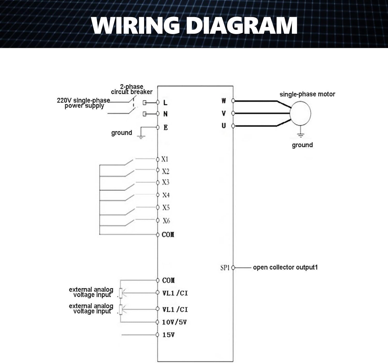
Figure 8.1: Product specifications as displayed on the unit.
| Feature | Detail |
|---|---|
| Model | AT1-4000X |
| Suitable Motor Power | 4 kW |
| Rated Voltage | AC220V (single phase) |
| Control Method | V/F Open Loop |
| Output Voltage Adjustable Method | PWM control |
| Rated Current | 20A |
| Maximum Output Frequency Range | 0-400Hz |
| Product Dimensions | 4.72 x 6.69 x 5.91 inches |
| Item Weight | 3.3 pounds |
9. Warranty and Support
For warranty information, please refer to the product packaging or contact your retailer. For technical support, troubleshooting assistance, or spare parts, please contact Walfront customer service through the official Walfront store or website. Provide your product model number (AT1-4000X) and purchase details for efficient service.


