1. Introduction
Welcome to the OWON XDS3104AE Digital Oscilloscope user manual. This document provides essential information for the safe and efficient operation of your new instrument. The XDS3104AE is a high-performance 4-channel digital oscilloscope featuring a 100 MHz bandwidth, 1 GS/s sample rate, 14-bit vertical resolution, and an 8-inch color LCD with optional multi-touch capabilities. It includes advanced triggering and bus decoding functions for I2C, SPI, RS232, and CAN protocols, making it suitable for a wide range of electronic testing and measurement applications.
2. Safety Information
To prevent personal injury and avoid damage to the instrument or connected devices, please read and follow these safety precautions:
- Grounding: Ensure the oscilloscope is properly grounded to prevent electric shock.
- Power Source: Use only the specified power cord and connect to a power source within the rated voltage range (100V - 240V AC, 50/60Hz).
- Probes: Use only probes rated for the voltage and current being measured. Do not touch exposed connections or components when power is applied.
- Environment: Operate the instrument in a well-ventilated area, away from moisture, dust, and direct sunlight. Avoid operating in explosive atmospheres.
- Maintenance: Refer all servicing to qualified personnel. Do not attempt to open or repair the instrument yourself.
3. Package Contents
Verify that all items listed below are present in your package:
- OWON XDS3104AE Digital Oscilloscope Unit
- Power Cord
- CD-ROM (with software and documentation)
- Quick Guide
- USB Cable
- Probes (quantity may vary)
- Probe Adjust Tool
- Battery (optional, 3.7V, 13200mA)
4. Product Overview
4.1 Key Features
- 100 MHz Bandwidth, 4 Channels
- 1 GS/s Real-time Sample Rate
- 14-bit High Resolution ADC
- 40M Record Length
- 45,000 wfms/s Waveform Refresh Rate
- 8-inch 800 x 600 High Resolution LCD (optional multi-touch screen)
- Low Background Noise
- Multi-trigger and Bus Decoding Functions (I2C, SPI, RS232, CAN)
- Multi-interface Integration: USB Host, USB Device, USB Port for PictBridge, LAN, AUX, VGA (optional)
- SCPI and LabVIEW Supported
4.2 Front Panel Layout
The front panel features the 8-inch color LCD display, control knobs, function buttons, and input channels. The intuitive layout allows for easy navigation and parameter adjustment.
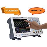
Figure 4.2.1: Front view of the OWON XDS3104AE Oscilloscope, showing the display, control panel, and input connectors.
4.3 Rear Panel Connections
The rear panel provides various connectivity options including the power input, USB ports for host and device connections, LAN port for network connectivity, AUX output, and an optional VGA output for external display.
5. Setup
5.1 Powering On
- Connect the provided power cord to the AC input on the rear panel of the oscilloscope and then to a suitable AC power outlet.
- If using the optional battery, ensure it is properly installed and charged.
- Press the power button located on the front panel to turn on the oscilloscope. The boot screen will appear, followed by the main waveform display.
5.2 Probe Connection and Compensation
- Connect the BNC connector of the probe to one of the input channels (CH1, CH2, CH3, or CH4) on the front panel.
- Attach the probe ground clip to the circuit ground.
- For accurate measurements, it is recommended to compensate the probes. Connect the probe tip to the probe compensation output (usually a square wave signal) on the front panel. Adjust the probe compensation trimmer until a flat-top square wave is displayed on the screen.
6. Operating Instructions
6.1 Basic Operation
- Vertical Controls: Use the vertical scale knobs (VOLTS/DIV) to adjust the vertical sensitivity for each channel. Use the position knobs to shift the waveform vertically.
- Horizontal Controls: Use the horizontal scale knob (SEC/DIV) to adjust the time base. Use the position knob to shift the waveform horizontally.
- Menu Navigation: Utilize the touchscreen or navigation buttons to access various menus for settings, measurements, and analysis functions.
6.2 Triggering
The trigger system synchronizes the oscilloscope to a specific point on the input signal, ensuring stable waveform display. The XDS3104AE supports multiple trigger types:
- Edge Trigger: Triggers on the rising or falling edge of a signal.
- Video Trigger: Triggers on standard video signals.
- Pulse Trigger: Triggers on pulses of specific width.
- Slope Trigger: Triggers on the rising or falling edge with a specific slope.
- Runt Trigger: Triggers on pulses that cross one threshold but fail to cross a second threshold before crossing the first again.
- Windows Trigger: Triggers when a signal enters or exits a specified voltage window.
- Timeout Trigger: Triggers when a signal remains high or low for a specified duration.
- Nth Edge Trigger: Triggers on the Nth edge of a burst.
- Logic Trigger: Triggers based on a logical combination of multiple input channels.
- Bus Triggers (I2C, SPI, RS232, CAN): Triggers on specific data patterns or conditions within serial bus communications.
To set up a trigger, press the 'Trigger' button or access the trigger menu via the touchscreen. Select the desired trigger type, source channel, and adjust parameters like level, slope, and mode (Auto, Normal, Single).
6.3 Bus Decoding
The XDS3104AE offers powerful serial bus decoding capabilities for I2C, SPI, RS232, and CAN protocols. This feature allows you to view decoded data directly on the screen, simplifying debugging of embedded systems.
- Access the 'Decode' menu from the main interface.
- Select the desired bus protocol (I2C, SPI, RS232, or CAN).
- Configure the relevant parameters such as source channels, baud rate, data format, and address settings according to your specific bus setup.
- The decoded data will be displayed alongside the waveform, often in a tabular format or overlaid on the signal.
6.4 Measurements
The oscilloscope provides various measurement tools:
- Automatic Measurements: Access the 'Measure' menu to select from a range of automatic measurements such as Vpp, Vmax, Vmin, Freq, Period, Rise Time, Fall Time, etc.
- Cursors: Use horizontal and vertical cursors to manually measure voltage and time differences on the waveform.
- Waveform Math: Perform mathematical operations on waveforms (+, -, *, /, FFT, Intg, Diff, Sqrt, and user-defined functions).
7. Maintenance
- Cleaning: Clean the instrument's exterior with a soft, damp cloth. Do not use abrasive cleaners or solvents. Ensure the unit is powered off and disconnected from the power source before cleaning.
- Battery Care (if applicable): If your unit includes a battery, follow proper charging and storage guidelines to maximize its lifespan. Avoid fully discharging the battery frequently.
- Software Updates: Periodically check the OWON official website for firmware updates to ensure optimal performance and access to new features.
8. Troubleshooting
This section addresses common issues you might encounter:
- No Power: Check the power cord connection and the power outlet. Ensure the power button is pressed. If using battery, check battery charge.
- No Waveform Display: Verify probes are correctly connected to the input channels and the circuit under test. Adjust vertical (VOLTS/DIV) and horizontal (SEC/DIV) scales. Check trigger settings.
- Unstable Waveform: Adjust trigger level and trigger mode. Ensure the trigger source is correctly selected.
- Incorrect Measurements: Perform probe compensation. Ensure correct probe attenuation settings (e.g., 1X, 10X) are selected on both the probe and the oscilloscope.
- Touchscreen Unresponsive: Try restarting the device. If the issue persists, contact support.
9. Specifications
| Parameter | Specification |
|---|---|
| Model | XDS3104AE |
| Bandwidth | 100 MHz |
| Sample Rate | 1 GS/s |
| Vertical Resolution (A/D) | 14 bits |
| Record Length | 40M |
| Waveform Refresh Rate | 45,000 wfms/s |
| Channels | 4 |
| Display | 8" color LCD, 800 x 600 pixels |
| Horizontal Scale (s/div) | 2ns/div - 1000s/div |
| Vertical Sensitivity | 1mV/div - 10V/div (at input) |
| Input Coupling | DC, AC, GND |
| Trigger Types | Edge, Video, Pulse, Slope, Runt, Windows, Timeout, Nth Edge, Logic, I2C, SPI, RS232, CAN |
| Communication Interface | USB host, USB device, USB port for PictBridge, Trig Out (P/F), LAN, VGA (optional) |
| Power Supply | 100V - 240V AC, 50/60Hz |
| Battery (optional) | 3.7V, 13200mA |
| Dimensions (W x H x D) | 340mm x 177mm x 90mm |
10. Warranty and Support
OWON products are designed and manufactured to high-quality standards. For warranty information, please refer to the warranty card included with your product or visit the official OWON website. For technical support, troubleshooting assistance, or service inquiries, please contact OWON customer service through their official channels. Keep your purchase receipt as proof of purchase for warranty claims.
Official OWON Website: www.owon.com