
1. Introduction
This manual provides detailed instructions for the installation, operation, and maintenance of your Texas Ranger TR-199MKI 40-Channel AM CB Radio. Please read this manual thoroughly before operating the unit to ensure proper use and to maximize its performance. The TR-199MKI is designed for reliable communication on the Citizen Band (CB) radio service.
2. Safety Information
- Antenna Installation: Ensure your CB antenna is properly installed and tuned for optimal performance and to prevent damage to the radio. Avoid operating the radio without a connected antenna.
- Power Supply: Connect the radio only to a 12-volt DC power source with negative ground. Incorrect voltage or polarity can damage the unit.
- Vehicle Operation: Do not operate the radio in a manner that distracts you from driving. Always prioritize safe vehicle operation.
- Hearing Protection: Prolonged exposure to high volume levels may cause hearing damage. Adjust the volume to a comfortable level.
- Interference: This device complies with Part 15 of the FCC Rules. Operation is subject to the condition that this device does not cause harmful interference.
3. Package Contents
Please check the package contents upon unpacking. If any items are missing or damaged, contact your dealer immediately.
- Texas Ranger TR-199MKI CB Radio
- Microphone
- Mounting Bracket Kit (with screws and washers)
- DC Power Cord
- User Manual
4. Controls and Indicators
Familiarize yourself with the front panel controls and indicators of your TR-199MKI radio.
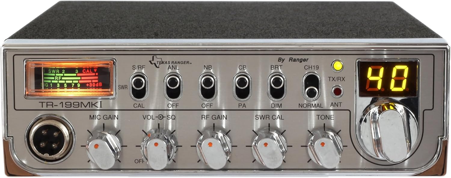
Figure 1: Front panel view of the Texas Ranger TR-199MKI CB Radio. This image displays the microphone input, various control knobs, switches, the channel display, and the S/RF-SWR meter.
- S/RF-SWR Meter: This meter displays the relative strength of incoming signals (S), your radio's RF output power (RF), and the Standing Wave Ratio (SWR) of your antenna system.
- SWR CAL Knob: Used in conjunction with the S/RF-SWR meter to calibrate the SWR reading for accurate antenna tuning.
- MIC GAIN Knob: Adjusts the sensitivity of the microphone. Turn clockwise to increase sensitivity.
- VOL-SQ Knob (Dual Concentric):
- Outer (VOL): Controls the receiver audio volume. Turn clockwise to increase volume.
- Inner (SQ): Controls the squelch level. Turn clockwise to suppress background noise when no signal is present.
- RF GAIN Knob: Adjusts the receiver's sensitivity to incoming signals. Turn counter-clockwise to reduce sensitivity, useful in areas with strong local signals.
- NB/ANL Switch: Activates the Noise Blanker (NB) and Automatic Noise Limiter (ANL) circuits to reduce impulse noise interference.
- CB/PA Switch: Selects between CB radio operation and Public Address (PA) mode. In PA mode, your voice from the microphone is amplified through an external PA speaker (not included).
- BRT/DIM Switch: Adjusts the brightness of the channel display and meter illumination.
- CH19/NORMAL Switch: Instantly selects Channel 19, the common emergency and highway information channel. Flip back to NORMAL to return to the previously selected channel.
- ANT Switch: (If present, typically for selecting between multiple antenna inputs, though this model usually has one).
- TX/RX Indicator: Illuminates red when transmitting (TX) and green when receiving (RX).
- Channel Display: Shows the currently selected operating channel number (1-40).
- Channel Selector Knob: Rotary knob used to select the desired operating channel.
5. Installation and Setup
Proper installation is crucial for optimal performance and safety.
5.1 Mounting the Radio
- Choose a secure location in your vehicle or operating area that does not obstruct driving or safety devices.
- Use the provided mounting bracket as a template to mark drilling locations.
- Drill pilot holes and secure the bracket using the supplied screws and washers.
- Slide the radio into the bracket and secure it with the thumb screws on the sides.
5.2 Power Connection
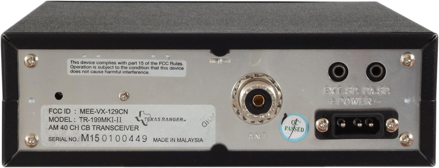
Figure 2: Rear panel view of the Texas Ranger TR-199MKI CB Radio, highlighting the power input, antenna connector, and external speaker/PA jacks.
- Locate the DC power cord. The red wire is positive (+12V DC) and the black wire is negative (ground).
- Connect the red wire to a switched +12V DC source in your vehicle (e.g., accessory fuse block).
- Connect the black wire to a good chassis ground point.
- Ensure all connections are secure and properly insulated.
5.3 Antenna Connection
- Connect a properly tuned 27 MHz CB antenna to the ANT connector (PL-259 type) on the rear of the radio.
- A well-tuned antenna is critical for both transmit performance and preventing damage to the radio's output stage.
5.4 Microphone Connection
- Plug the microphone connector firmly into the 4-pin microphone jack on the front panel of the radio.
6. Operating Instructions
6.1 Basic Operation
- Power On: Turn the outer VOL knob clockwise until a click is heard and the display illuminates.
- Volume Adjustment: Continue turning the outer VOL knob to achieve a comfortable listening level.
- Squelch Adjustment: Turn the inner SQ knob clockwise until the background static noise disappears. This is the squelch threshold. Turn it counter-clockwise to hear weaker signals.
- Channel Selection: Use the Channel Selector knob to choose your desired operating channel (1-40).
- Transmit: To transmit, press and hold the Push-To-Talk (PTT) button on the microphone. Speak clearly into the microphone. The TX/RX indicator will light red. Release the PTT button to receive.
6.2 Advanced Functions
- RF Gain: Adjust the RF GAIN knob to control the sensitivity of the receiver. In areas with strong local signals, reducing RF Gain can prevent overloading and improve clarity.
- SWR Calibration:
- Select an unused channel (e.g., Channel 20).
- Set the S/RF-SWR meter switch to CAL.
- Press and hold the PTT button on the microphone.
- While holding PTT, adjust the SWR CAL knob until the meter needle points to the 'SET' or 'CAL' mark.
- Release PTT.
- Set the S/RF-SWR meter switch to SWR.
- Press and hold PTT again and read the SWR value. An SWR of 1.5:1 or lower is generally good. Higher values indicate a poorly tuned antenna or connection issue.
- NB/ANL: Activate the NB/ANL switch to reduce electrical interference from vehicle ignition systems or other sources.
- PA Function: Connect an external PA speaker to the PA jack on the rear of the radio. Switch the CB/PA switch to PA. Your voice from the microphone will now be broadcast through the external speaker.
- CH19: Use the CH19/NORMAL switch for quick access to Channel 19 for highway information or emergency communication.
7. Maintenance
- Cleaning: Use a soft, damp cloth to clean the exterior of the radio. Do not use abrasive cleaners or solvents.
- Connections: Periodically check all power, antenna, and microphone connections to ensure they are secure and free from corrosion.
- Antenna System: Regularly inspect your antenna and coaxial cable for damage. A damaged antenna system can degrade performance and potentially harm the radio.
- Fuse Replacement: If the radio does not power on, check the fuse in the DC power cord. Replace it with a fuse of the same type and rating (typically 2-3 Amperes).
8. Troubleshooting
| Problem | Possible Cause | Solution |
|---|---|---|
| Radio does not power on. | No power, blown fuse, incorrect wiring. | Check power connections, replace fuse, verify wiring polarity. |
| No reception or very weak signals. | Squelch too high, antenna disconnected/damaged, volume too low, RF Gain too low. | Adjust SQ knob counter-clockwise, check antenna connection, increase volume, increase RF Gain. |
| Cannot transmit or poor transmission. | Microphone not connected, PTT button faulty, high SWR, antenna issue. | Check microphone connection, test PTT, perform SWR calibration, inspect antenna. |
| Excessive static or noise. | Squelch too low, NB/ANL off, electrical interference. | Increase SQ, activate NB/ANL, check vehicle's electrical system for noise sources. |
9. Specifications
- Model: TR-199MKI
- Channels: 40 AM
- Input Voltage: 13.8V DC nominal
- Weight: 5.66 Pounds (approximately 2.57 kg)
- UPC: 734168008041
- Compatible Devices: Other CB radios operating on the same frequency range.
10. Warranty and Support
For warranty information, technical assistance, or service inquiries regarding your Texas Ranger TR-199MKI CB Radio, please contact your authorized Texas Ranger dealer or visit the official Texas Ranger website. Keep your purchase receipt as proof of purchase for warranty claims.


