1. Introduction
This manual provides detailed instructions for the installation, operation, and maintenance of the Walfront Stepper Motor Driver. This module is designed to control 8, 11, 14, 16, and 17 series stepper motors, offering precise control with adjustable current and microstep settings. It features integrated protection mechanisms for enhanced reliability.
2. Product Overview
The Walfront Stepper Motor Driver is a robust controller module featuring a wide input voltage range of DC 9-42V and an adjustable output current from 0.5A to 4A. Key features include:
- Adjustable Current: Output current selectable from 0.5A to 4A.
- Microstep Resolution: Supports up to 32 microstep resolution for smooth motor operation.
- Protection Features: Includes overheat, overcurrent, short circuit, and input voltage anti-reverse protection.
- Efficient Heat Dissipation: Equipped with a large area heat sink to manage thermal performance.
- Automatic Half Current: Reduces heat generation during idle periods.

Figure 2.1: Walfront Stepper Motor Driver with dimensions. The driver measures approximately 9.5cm (3.74 inches) in length, 7cm (2.75 inches) in width, and 2.7cm (1.06 inches) in height.
3. Safety Information
Please read and understand all safety precautions before installing or operating this device. Failure to follow these instructions may result in electric shock, fire, or damage to the product.
- Ensure the power supply is disconnected before making any connections or adjustments.
- Verify correct polarity for all power connections to prevent damage from reverse voltage.
- Do not exceed the specified input voltage range (DC 9-42V).
- Avoid touching the heat sink during operation, as it may become hot.
- Install the driver in a well-ventilated area to ensure proper heat dissipation.
- This device is intended for use by qualified personnel familiar with electronic components and stepper motor control.
4. Specifications
| Parameter | Value |
|---|---|
| Input Voltage | DC 9-42V |
| Input Current | 5A (recommended) |
| Output Current | 0.5-4A |
| Maximum Power | 160W |
| Microstep Resolution | 1, 2/A, 2/B, 4, 8, 16, 32 |
| Dimensions (Approx.) | 9.5 x 7 x 2.7 cm (3.74 x 2.75 x 1.06 inches) |
| Weight (Approx.) | 148g (4.16 ounces) |
| Protection Features | Overheat, Overcurrent, Short Circuit, Input Voltage Anti-Reverse |
5. Setup and Wiring
Before connecting the driver, ensure all power sources are disconnected. Refer to the wiring diagram below for proper connections.
5.1. Wiring Diagram

Figure 5.1: General wiring diagram showing connections between a controller and the stepper motor driver, and various stepper motor configurations (4-wire, 6-wire, 8-wire). Note: The EN (Enable) end should not be connected.
Terminal Descriptions:
- VCC, GND: Power input (DC 9-42V). VCC is positive, GND is negative.
- A+, A-, B+, B-: Stepper motor coil connections. Connect according to your motor's wiring.
- PUL+(+5V), PUL-(PUL): Pulse input. PUL+ connects to the positive pulse signal, PUL- to the negative pulse signal.
- DIR+(+5V), DIR-(DIR): Direction input. DIR+ connects to the positive direction signal, DIR- to the negative direction signal.
- ENA+(+5V), ENA-(ENA): Enable input. ENA+ connects to the positive enable signal, ENA- to the negative enable signal. Note: The EN end should not be connected as per the diagram.
- PWR/ALARM: Power/Alarm indicator.
Ensure all connections are secure and correctly polarized before applying power.
6. Operating Instructions
The Walfront Stepper Motor Driver's operating parameters are configured using the onboard DIP switches. These switches control the output current and microstep resolution.
6.1. Setting Microstep Resolution
The microstep resolution is set using DIP switches SW1, SW2, and SW3. Refer to the table below and the product image for switch positions.
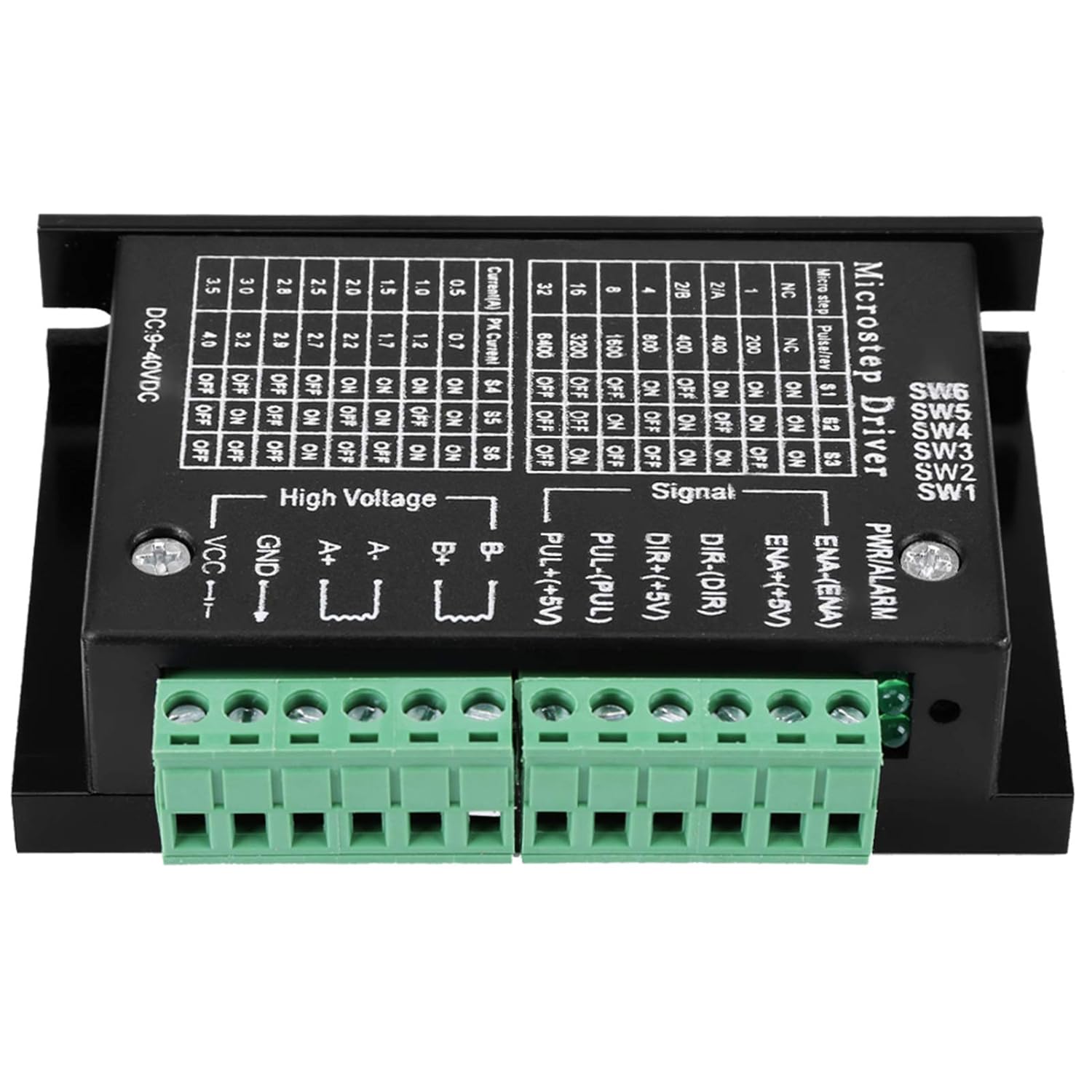
Figure 6.1: Top view of the stepper motor driver showing the DIP switches and their corresponding tables for microstep resolution and current settings.
| Microstep | Pulses/Rev (200 steps/rev motor) | SW1 | SW2 | SW3 |
|---|---|---|---|---|
| NC | NC | ON | ON | ON |
| 1 | 200 | ON | ON | OFF |
| 2/A | 400 | ON | OFF | ON |
| 2/B | 400 | ON | OFF | OFF |
| 4 | 800 | OFF | ON | ON |
| 8 | 1600 | OFF | ON | OFF |
| 16 | 3200 | OFF | OFF | ON |
| 32 | 6400 | OFF | OFF | OFF |
6.2. Setting Output Current
The output current (peak current) is set using DIP switches SW4, SW5, and SW6. Refer to the table below and the product image for switch positions.
| Current (A) | Peak Current (A) | SW4 | SW5 | SW6 |
|---|---|---|---|---|
| 0.5 | 0.7 | ON | ON | ON |
| 1.0 | 1.2 | ON | ON | OFF |
| 1.5 | 1.7 | ON | OFF | ON |
| 2.0 | 2.2 | ON | OFF | OFF |
| 2.5 | 2.7 | OFF | ON | ON |
| 2.8 | 3.0 | OFF | ON | OFF |
| 3.0 | 3.2 | OFF | OFF | ON |
| 3.5 | 4.0 | OFF | OFF | OFF |
Important: Always adjust DIP switch settings when the power is disconnected to prevent damage to the driver or motor.
7. Maintenance
The Walfront Stepper Motor Driver is designed for reliable operation with minimal maintenance. Follow these guidelines to ensure longevity:
- Keep the driver clean and free from dust and debris. Use a soft, dry cloth for cleaning.
- Ensure adequate airflow around the heat sink to prevent overheating.
- Periodically check all wiring connections for tightness and signs of wear or corrosion.
- Avoid exposing the device to excessive moisture or extreme temperatures.
8. Troubleshooting
If you encounter issues with your stepper motor driver, refer to the following common problems and solutions:
| Problem | Possible Cause | Solution |
|---|---|---|
| Motor not moving or erratic movement | Incorrect wiring; insufficient power; incorrect current/microstep settings; faulty motor. | Check all wiring against the diagram. Verify power supply voltage and current. Review DIP switch settings for current and microstep. Test motor independently if possible. |
| Driver overheating | Insufficient ventilation; excessive load; incorrect current setting. | Ensure proper airflow around the heat sink. Reduce motor load. Verify the output current setting is appropriate for the motor. |
| Motor makes noise but doesn't turn | Motor phase wiring incorrect; motor stalled. | Double-check motor coil connections (A+, A-, B+, B-). Ensure the motor is not mechanically obstructed. |
| No power indicator light | No power input; reverse polarity; faulty driver. | Check power supply connection and voltage. Verify correct input polarity. If issues persist, the driver may be faulty. |
9. Warranty and Support
Walfront products are manufactured to high-quality standards. For warranty information or technical support, please contact your retailer or the Walfront customer service department. Keep your purchase receipt for warranty claims.
For further assistance, please visit the Walfront Store on Amazon.


