
1. Introduction
This manual provides essential information for the installation, operation, and maintenance of your NB POWER 48-72V 60A Brushless DC Motor Controller and UKC1 Color Display. This system is designed for electric bicycles and scooters utilizing 2000W to 3000W hub motors or conversion kits. Please read these instructions carefully before use to ensure proper function and safety.
2. Product Overview
The NB POWER controller system includes a high-performance brushless DC motor controller and a UKC1 color display unit, along with necessary accessories for installation.
2.1 Components Included
- 1 x 48/72V 60A Brushless Motor Controller
- 1 x UKC1 Color Display
- 1 x Bag for Controller
- Connection parts

Image: Contents of the NB POWER controller kit, including the controller, UKC1 display, bag, and connection parts, neatly packed in a box.
2.2 Controller Features
- 48/72V 60A Brushless Sine Wave Controller
- Suitable for 2000W-3000W E-bike Hub Motors
- Supports Regenerative Function (requires UKC1 display)

Image: The NB POWER 48-72V 60A Brushless DC Motor Controller, showing its finned aluminum casing and a label detailing its technical specifications.
2.3 UKC1 Color Display Features
- Color display for clear visibility
- Displays riding speed, single mileage, and cumulative mileage
- Shows riding time, power-assist gear, motor power, and temperature
- Indicates battery voltage and charge status
- Displays brake status and ambient temperature

Image: The UKC1 Color Display, illuminated and showing various metrics such as speed, trip distance, assist level, battery charge, and time.

Image: A black fabric bag designed to house the e-bike controller, featuring a zipper closure and mounting straps.
3. Specifications
| Parameter | Value |
|---|---|
| Maximum Current | 60 ± 1A |
| Rated Voltage | DC 48-72V |
| Rated Current | 30A |
| Speed Set | 1-4.2V |
| Brake Input | LOW-LEVEL |
| Low Voltage Protection | DC 50 ± 0.5V |
| Operating Conditions | -40~80°C |
| Certification | CE |
| Attribute | Value |
|---|---|
| Brand Name | NB POWER |
| Material | Plastic (for display/connectors) |
| Manufacturer | niubo power |
| Part Number | NBP-KT-CTT |
| ASIN | B07FS99P89 |
3.1 Dimensions

Image: Diagram showing the dimensions of the NB POWER 60A Brushless DC Motor Controller: approximately 18.5 cm (length) x 11 cm (width) x 5.2 cm (height).

Image: Technical drawing illustrating the dimensions of the UKC1 Color Display (approx. 111mm x 87mm x 15mm) and its associated control panel (approx. 39.35mm x 44mm).
4. Setup and Installation
Proper installation is crucial for the safe and efficient operation of your e-bike system. If you are unsure about any steps, consult a qualified technician.
4.1 Safety Precautions
- Always disconnect the battery before performing any wiring or installation.
- Ensure all connections are secure and insulated to prevent short circuits.
- Verify voltage compatibility between the controller, motor, and battery.
- Mount the controller in a location protected from water and physical damage, ideally within the provided bag.
4.2 Wiring Diagram
Refer to the following diagram for correct wiring connections. Each wire is labeled for identification.
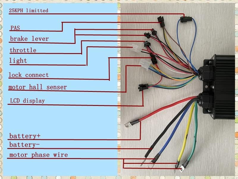
Image: A detailed wiring diagram illustrating the connections for the NB POWER Ebike Controller. Labels include 25KPH limited, PAS, brake lever, throttle, light, lock connect, motor hall sensor, LCD display, battery+, battery-, and motor phase wire.
- Battery Connection: Connect the thick red wire to the battery positive (+) and the thick black wire to the battery negative (-).
- Motor Phase Wires: Connect the three thick motor phase wires (typically green, blue, yellow) from the controller to the corresponding motor phase wires.
- Motor Hall Sensor: Connect the motor hall sensor cable to the designated port on the controller.
- UKC1 LCD Display: Connect the UKC1 display cable to the controller's LCD display port. This connection is essential for activating the regenerative function and viewing operational data.
- Throttle: Connect the throttle cable to the throttle port.
- Brake Levers: Connect the brake lever cables to the brake input ports. These typically provide a low-level signal to cut motor power when braking.
- PAS (Pedal Assist Sensor): Connect the PAS sensor cable if your e-bike uses pedal assist.
- Light: Connect the light cable if applicable.
- Lock Connect: Connect the ignition lock wire if your system includes one.
- 25KPH Limited: This wire, if present, can be connected to limit the speed to 25 km/h. Consult local regulations regarding speed limits.
After making all connections, double-check for proper seating and insulation before reconnecting the battery.
5. Operating Instructions
The UKC1 Color Display serves as your primary interface for monitoring and controlling your e-bike system.
5.1 UKC1 Display Functions
Once powered on, the UKC1 display will show various cycling parameters:
- Riding Speed: Current speed in km/h or mph.
- Mileage: Single trip mileage and cumulative total mileage.
- Riding Time: Duration of the current ride.
- Power-Assist Gear: Current level of pedal assistance.
- Motor Power and Temperature: Real-time motor output and temperature.
- Battery Voltage and Charge Status: Current battery voltage and remaining charge level.
- Brake Status: Indication when brakes are applied.
- Ambient Temperature: Current environmental temperature.
Consult the specific UKC1 display manual (if provided separately) for detailed instructions on navigating menus, changing settings, and adjusting assist levels.
5.2 Regenerative Function
This controller supports a regenerative braking function, which can recharge the battery during braking or downhill riding. This feature is activated and managed through the UKC1 LCD Display. Ensure the display is correctly connected and configured to utilize this function.
6. Maintenance
Regular maintenance helps ensure the longevity and reliable performance of your e-bike controller and display.
- Keep Clean: Periodically wipe down the controller and display with a soft, dry cloth. Avoid using harsh chemicals or abrasive materials.
- Check Connections: Regularly inspect all wiring connections for tightness and signs of wear or corrosion. Loose connections can lead to intermittent operation or damage.
- Protect from Elements: While the controller is designed for outdoor use, avoid prolonged exposure to heavy rain or direct water spray. Ensure the controller is housed in the provided bag or a similar protective enclosure.
- Avoid Overheating: Ensure the controller has adequate airflow, especially during extended periods of high power usage. Do not obstruct the cooling fins.
- Battery Care: Follow your battery manufacturer's guidelines for charging and storage to ensure optimal system performance.
7. Troubleshooting
If you encounter issues with your NB POWER controller system, refer to the following common troubleshooting steps:
| Problem | Possible Cause | Solution |
|---|---|---|
| Motor not responding / No power |
|
|
| Display not turning on |
|
|
| Motor runs intermittently or roughly |
|
|
| Regenerative braking not working |
|
|
For issues not covered here, or if troubleshooting steps do not resolve the problem, please contact customer support.
8. Warranty and Support
Specific warranty details for this product are not provided in this manual. Please refer to your purchase documentation or contact the seller/manufacturer directly for warranty information and support inquiries.
Manufacturer: niubo power