
1. Introduction and Product Overview
This manual provides essential information for the safe and efficient operation, installation, and maintenance of your Geko G01025 Electric Diesel/Oil Transfer Pump. This 600W electric pump is designed for transferring diesel fuel and oil. It is characterized by its durability and solid performance, constructed from high-quality materials.

Image: The main Geko G01025 electric pump unit, featuring an integrated flow meter and a sturdy frame for stability during operation.
2. Safety Instructions
Read all safety warnings and instructions before using this product. Failure to follow these instructions may result in electric shock, fire, serious injury, or property damage.
- Electrical Safety: Ensure the power supply matches the pump's specifications (230V, 50Hz). Do not operate the pump with damaged cables or plugs. Always connect to a grounded outlet.
- Fluid Compatibility: This pump is designed for diesel and oil transfer only. Do not use with gasoline, alcohol, water, corrosive chemicals, or any other flammable liquids not specified, as this may cause fire or explosion.
- Ventilation: Operate the pump in a well-ventilated area to prevent the accumulation of hazardous fumes.
- Personal Protective Equipment: Wear appropriate personal protective equipment (PPE) such as gloves and eye protection when handling fuels and oils.
- Spill Prevention: Always ensure all connections are secure to prevent leaks and spills. Have spill containment materials readily available.
- Children and Bystanders: Keep children and unauthorized persons away from the operating area.
- Emergency Stop: Familiarize yourself with the location and operation of the ON/OFF switch for quick shutdown in emergencies.
3. Package Contents
Carefully unpack all components and check against the list below. If any parts are missing or damaged, contact your supplier immediately.
- Geko G01025 Electric Transfer Pump Unit with Integrated Meter
- Suction Hose (Clear, reinforced)
- Discharge Hose (Black)
- Fuel Nozzle
- Various Fittings (Brass connectors)
- Hose Clamps
- Seals/Gaskets

Image: An assortment of brass fittings, metal hose clamps, and rubber O-rings, essential for connecting hoses to the pump unit.

Image: A coiled clear, reinforced hose, typically used as the suction line for drawing fluid into the pump.

Image: A coiled black hose, commonly used as the discharge line for delivering fluid from the pump.
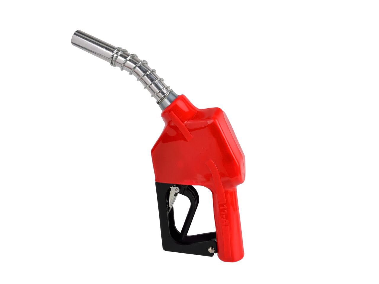
Image: A red and black fuel dispensing nozzle, designed for controlled delivery of diesel or oil.
4. Setup Instructions
Follow these steps to correctly assemble and prepare your pump for operation.
- Secure Placement: Place the pump unit on a stable, level surface near the fluid source and destination. Ensure adequate ventilation.
- Connect Suction Hose: Attach one end of the clear suction hose to the inlet port of the pump. Use appropriate fittings and hose clamps to ensure a tight, leak-free connection.
- Connect Discharge Hose: Attach one end of the black discharge hose to the outlet port of the pump. Secure with fittings and hose clamps.
- Attach Nozzle: Connect the fuel nozzle to the free end of the discharge hose, ensuring a secure connection.
- Submerge Suction End: Place the free end of the suction hose into the fluid source (e.g., diesel tank). Ensure the end is fully submerged and clear of debris.
- Electrical Connection: Plug the pump's power cord into a suitable, grounded 230V, 50Hz electrical outlet.
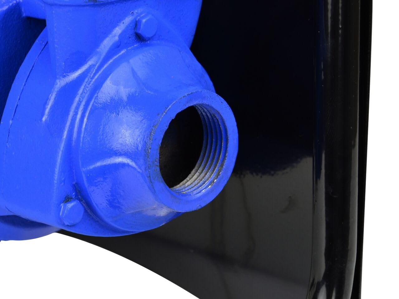
Image: A close-up view of the pump's threaded inlet or outlet port, where hoses and fittings are connected.
5. Operating Instructions
Follow these steps for safe and effective fluid transfer.
- Pre-Operation Check: Before starting, verify all hose connections are tight, the suction hose is properly submerged, and the discharge nozzle is ready at the receiving container.
- Power On: Locate the ON/OFF switch on the pump's control panel. Flip the switch to the 'ON' (I) position to start the pump.
- Fluid Transfer: The pump will begin to draw fluid from the source and deliver it through the discharge hose and nozzle. Monitor the flow and the integrated meter.
- Monitor Meter: The integrated meter displays the volume of fluid transferred. The 'LITER' display shows the current transfer, while 'TOTAL' shows the cumulative volume.
- Stopping Transfer: Once the desired volume is transferred or the receiving container is full, flip the ON/OFF switch to the 'OFF' (O) position to stop the pump.
- Post-Operation: Remove the nozzle from the receiving container. Allow any residual fluid to drain. Disconnect the power supply.

Image: The pump's control panel, featuring a green 'ON' button (I) and a red 'OFF' button (O) for easy operation. A label indicates electrical specifications and model number.

Image: A close-up of the pump's integrated flow meter, showing 'LITER' for current measurement and 'TOTAL' for cumulative volume, along with a warning about non-commercial use.
6. Maintenance
Regular maintenance ensures the longevity and reliable performance of your pump.
- Cleaning: After each use, wipe down the pump and hoses to remove any spills or residue. Do not use harsh chemicals that may damage components.
- Inspect Hoses and Connections: Periodically check hoses for cracks, wear, or damage. Ensure all fittings and clamps remain tight to prevent leaks. Replace worn components as necessary.
- Filter Inspection: If your suction hose includes a filter, inspect it regularly for blockages and clean or replace as needed to maintain optimal flow.
- Storage: When not in use, store the pump in a clean, dry, and protected area, away from direct sunlight and extreme temperatures. Ensure all fluid is drained from the pump and hoses before storage.
7. Troubleshooting
Refer to the table below for common issues and their potential solutions.
| Problem | Possible Cause | Solution |
|---|---|---|
| Pump does not start | No power supply Damaged power cord/switch | Check power connection and outlet Inspect power cord and switch; replace if damaged |
| Low flow or no flow | Suction hose not submerged Air leak in suction line Clogged filter Hose kinked or blocked | Ensure suction hose is fully submerged Check all suction connections for tightness Clean or replace filter Straighten hoses; clear any blockages |
| Fluid leaks | Loose hose connections Damaged hose or seal | Tighten all hose clamps and fittings Inspect hoses and seals; replace damaged parts |
| Meter inaccurate | Air in the system Meter malfunction | Ensure no air is being drawn into the pump Contact customer support for service |
8. Specifications
Technical specifications for the Geko G01025 Electric Diesel/Oil Transfer Pump.
| Specification | Value |
|---|---|
| Model Number | Geko_G01025 |
| Manufacturer | Firma Handlowa GEKO |
| Power | 600 W |
| Voltage | 230V |
| Frequency | 50Hz |
| Flow Rate | 3600 l/h |
| Package Dimensions | 35 x 35 x 15 cm |
| Weight | 12 kg |
| ASIN | B07FR4R9LZ |
9. Warranty and Support
This product is manufactured to high-quality standards. For warranty information or technical support, please refer to the documentation provided with your purchase or contact the manufacturer directly. Keep your proof of purchase for any warranty claims.
