Introduction
This manual provides essential information for the safe and effective operation and maintenance of your Geko G02180 Moto ATV Lift. Please read this manual thoroughly before initial use to ensure proper handling and to prevent injury or damage to the equipment. This lift is designed for safely raising and supporting motorcycles and ATVs within its specified weight and height limits.
Safety Information
Always prioritize safety when operating the Geko G02180 Moto ATV Lift. Failure to follow these safety guidelines may result in serious injury or property damage.
- Read and understand all instructions before operating the lift.
- Ensure the lift is placed on a firm, level, and stable surface.
- Do not exceed the maximum weight capacity of 680 kg (1500 lbs).
- Always secure the motorcycle or ATV properly on the lift platform before raising.
- Keep hands and feet clear of moving parts during operation.
- Do not work under a vehicle supported only by the lift. Use additional jack stands for safety.
- Inspect the lift for damage or wear before each use. Do not use if damaged.
- Store the lift in a dry, safe place when not in use.
Parts Identification
Familiarize yourself with the components of your Geko G02180 Moto ATV Lift.

Figure 1: Overall View of the Geko G02180 Lift. This image displays the lift in its fully lowered state, highlighting the robust frame, the blue lifting arms, and the black rubber-padded support platforms. The hydraulic pump lever and release valve are visible towards the rear.

Figure 2: Lifting Arms and Support Platforms. A detailed view of the blue scissor-style lifting arms and the black, ribbed rubber support pads designed to securely hold the motorcycle or ATV frame without scratching.
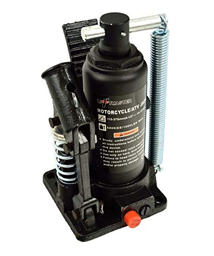
Figure 3: Hydraulic Bottle Jack. This image shows the integrated hydraulic bottle jack, which provides the lifting power. It includes the pumping mechanism, release valve (red knob), and safety spring.
Setup
- Unpacking: Carefully remove all components from the packaging. Inspect for any shipping damage.
- Assembly (if required): The Geko G02180 lift typically comes pre-assembled. Ensure all bolts and fasteners are tight before first use. Refer to any included assembly diagrams if partial assembly is required.
- Placement: Position the lift on a hard, flat, and level surface capable of supporting the combined weight of the lift and the vehicle.
- Check Hydraulic Fluid: Ensure the hydraulic fluid level is adequate. If low, consult the maintenance section for proper fluid type and refilling instructions.
Operating Instructions
Raising a Vehicle
- Position the vehicle centrally on the lift's support platforms, ensuring stability. The rubber pads should make full contact with the vehicle's frame or designated lifting points.
- Close the hydraulic release valve by turning it clockwise until it is fully tightened.
- Insert the handle into the pump socket.
- Pump the handle up and down to raise the lift. Continue pumping until the desired height is reached, or the lift reaches its maximum extension.
- Once raised, engage any safety locking mechanisms if available on your model to prevent accidental lowering.
- For extended work, always place additional jack stands under the vehicle for maximum safety.
Lowering a Vehicle
- Ensure the area around the lift is clear of obstructions and personnel.
- If safety locks were engaged, disengage them carefully.
- Slowly turn the hydraulic release valve counter-clockwise to gradually lower the lift. Do not open the valve too quickly, as this can cause the vehicle to drop rapidly.
- Continue lowering until the lift is fully retracted and the vehicle is resting on the ground.
- Remove the vehicle from the lift.
Maintenance
- Cleaning: Keep the lift clean and free of dirt, grease, and debris.
- Lubrication: Periodically lubricate pivot points and moving parts with a light machine oil to ensure smooth operation.
- Hydraulic Fluid: Check the hydraulic fluid level regularly. If low, refill with a high-quality hydraulic jack oil. Consult the manufacturer's recommendations for specific fluid types.
- Inspection: Before each use, inspect the lift for any signs of damage, cracks, bends, or excessive wear. Check all bolts and fasteners for tightness.
- Storage: Store the lift in a dry, protected area to prevent rust and corrosion.
Troubleshooting
| Problem | Possible Cause | Solution |
|---|---|---|
| Lift will not raise | Hydraulic release valve open; Low hydraulic fluid; Air in hydraulic system; Overload | Close valve; Refill fluid; Bleed air from system (consult manufacturer's guide); Reduce load (do not exceed capacity) |
| Lift lowers slowly or uncontrollably | Release valve not fully closed; Internal hydraulic leak; Contaminated fluid | Ensure valve is fully closed; Contact qualified service personnel; Replace fluid and bleed system |
| Squeaking or grinding noises | Lack of lubrication on pivot points | Lubricate all moving parts and pivot points |
Specifications
- Model Number: Geko_G02180
- Brand: Geko
- Lifting Range: 115 mm (minimum) to 375 mm (maximum)
- Maximum Load Capacity: 680 kg (1500 lbs)
- Package Dimensions: 93 x 49 x 28 cm
- Weight: 29.6 kg
- Manufacturer: Firma Handlowa GEKO
- Origin: Made in Poland
Warranty and Support
For warranty information and customer support, please refer to the documentation provided with your purchase or contact the manufacturer directly. Information regarding spare parts availability is not provided in the product details.
Manufacturer: Firma Handlowa GEKO
For further assistance, please visit the official Geko website or contact their customer service department.


