1. Introduction
This manual provides essential instructions for the safe and effective operation of the Fluke 1663 US Multi-Function Installation Tester. This device is engineered for comprehensive electrical installation testing, ensuring compliance with relevant local regulations and safety standards. Please read this manual thoroughly before using the tester.
2. Safety Information
Always adhere to local safety regulations and electrical standards when operating the Fluke 1663 US tester. Failure to do so may result in injury, damage to the device, or inaccurate measurements.
- Read and understand all instructions and warnings in this manual before initial use.
- Do not use the tester if it appears damaged, operates abnormally, or if the test leads are compromised.
- Ensure all test lead connections are secure and properly inserted to prevent electric shock or damage.
- Always disconnect power to the circuit under test before making connections for insulation or continuity measurements.
- Observe all warnings and precautions marked directly on the tester's casing.
3. Package Contents
Verify that all items listed below are present in your product package:
- Fluke 1663 US Multi-Function Installation Tester
- US Power Cord
- Test Leads (typically included for various measurements)
- User Manual (this document)
4. Product Overview
The Fluke 1663 US is a robust and versatile multi-function tester designed for a wide range of electrical installation measurements. Familiarize yourself with its components for optimal use.
4.1 Front Panel and Display
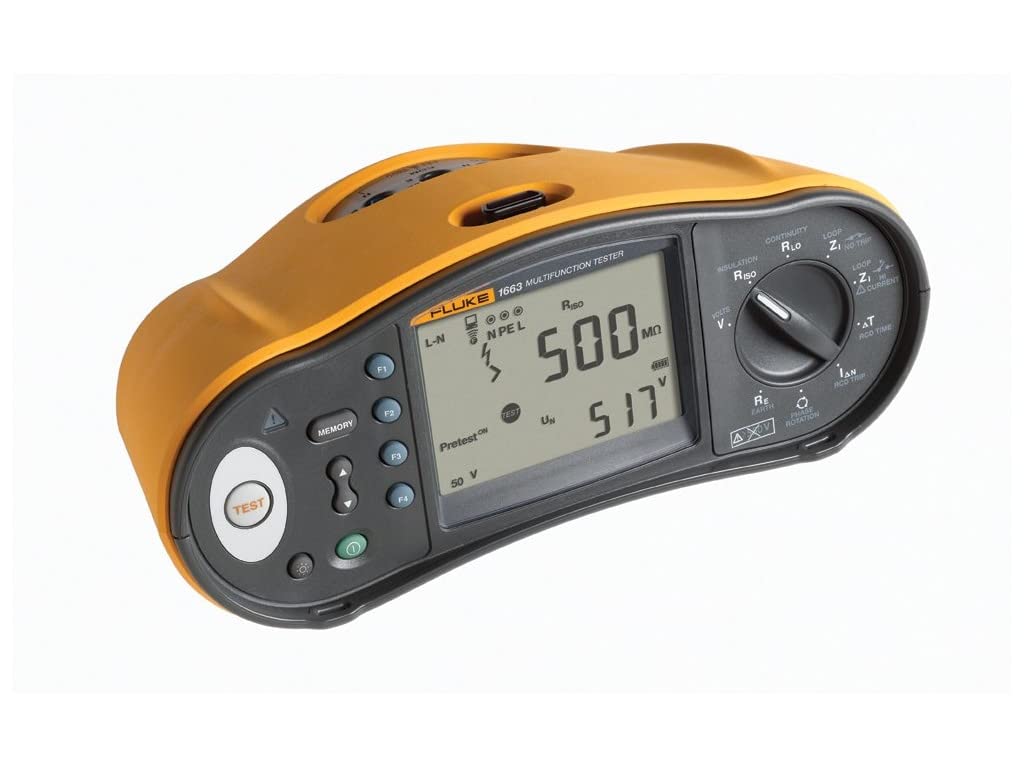
Image Description: A front-angled view of the Fluke 1663 US Multi-Function Installation Tester. The device features a durable yellow and dark gray casing. A prominent digital display shows measurement results, including "500 MΩ" and "517 V", along with status indicators like "Pretest ON" and "50 V". To the left of the display are the circular "TEST" button and the "MEMORY" button, accompanied by navigation arrows. On the right side, a large rotary dial allows selection of various measurement functions, such as Continuity, Insulation, Loop, RCD Time, Earth Resistance, and Phase Rotation. Several input terminals and additional function buttons are visible around the display and dial area.
The main display provides clear readings of measurement results and operational status. The large rotary dial is used to select the desired test function.
- TEST Button: Initiates the selected measurement.
- MEMORY Button: Used to store and recall test results.
- Rotary Dial: Selects various test functions, including:
- CONTINUITY RLO (Resistance of Live-Neutral/Earth)
- INSULATION RISO (Insulation Resistance)
- LOOP Z1 NO TRIP (Loop Impedance without RCD tripping)
- LOOP ZI CURRENT (Loop Impedance with current measurement)
- ΔT RCD TIME (RCD Trip Time)
- RE EARTH (Earth Resistance)
- PHASE ROTATION (Phase Sequence)
- Display Indicators: Shows connection status (L-N, N PE L), Pretest status, voltage levels (e.g., 50 V), and measurement values (e.g., 500 MΩ, 517 V).
5. Setup
5.1 Powering the Device
Insert the required batteries into the battery compartment, typically located on the rear of the tester. Ensure correct polarity as indicated inside the compartment. The device may also operate via the provided US Power Cord for certain functions or charging.
5.2 Connecting Test Leads
Connect the appropriate test leads to the input terminals on the tester. Always ensure that connections are secure and fully inserted before performing any tests to guarantee accurate readings and safe operation.
6. Operating Instructions
The Fluke 1663 US offers various testing modes for electrical installations. Select the desired function using the rotary dial on the front panel.
6.1 Continuity Testing (CONTINUITY RLO)
This function measures the resistance of protective conductors and equipotential bonding.
- Turn the rotary dial to `CONTINUITY RLO`.
- Connect the test leads to the circuit under test, typically across L-N or N-PE inputs.
- Press the `TEST` button to initiate the measurement.
- Read the resistance value displayed on the screen.
6.2 Insulation Resistance Testing (INSULATION RISO)
Measures the insulation resistance between conductors. The tester includes an `Insulation PreTest` feature to prevent damage to inadvertently connected appliances.
- Ensure the circuit under test is completely de-energized.
- Turn the rotary dial to `INSULATION RISO`.
- Connect the test leads to the conductors between which insulation resistance is to be measured.
- Press the `TEST` button. If the `Pretest ON` feature detects connected appliances, the test will stop, and a visual/audible warning will be provided.
- Read the insulation resistance value (e.g., `500 MΩ`) on the display.
6.3 Loop Impedance Testing (LOOP Z1 NO TRIP, LOOP ZI CURRENT)
Measures the impedance of the fault loop, crucial for verifying protective device operation.
- Select the desired Loop Impedance test function on the rotary dial.
- Connect the test leads to the live, neutral, and earth terminals of the circuit.
- Press the `TEST` button.
- Read the loop impedance value displayed.
6.4 RCD Testing (ΔT RCD TIME, Type B)
Tests Residual Current Devices (RCDs) for trip time and current. This model supports smooth DC sensitive RCDs (Type B).
- Select `ΔT RCD TIME` or other RCD test functions on the rotary dial.
- Connect the test leads to the RCD circuit.
- Press the `TEST` button.
- Observe the trip time and current values on the display.
6.5 Earth Resistance Testing (RE EARTH)
Measures the resistance of the earth electrode system.
- Turn the rotary dial to `RE EARTH`.
- Connect the necessary test leads and auxiliary electrodes according to the specific earth resistance test method being used.
- Press the `TEST` button.
- Read the earth resistance value on the display.
6.6 Phase Rotation Testing (PHASE ROTATION)
Determines the phase sequence in three-phase electrical systems.
- Turn the rotary dial to `PHASE ROTATION`.
- Connect the test leads to the three phases of the system.
- The display will indicate the detected phase sequence.
6.7 Auto Test Function
The `Auto Test` feature streamlines the testing process by performing a sequence of up to five required installation tests in one go. This includes selectable Type A, AC, and RCD Auto Test, significantly reducing manual connections and overall test time.
- Select the `Auto Test` mode on the rotary dial (if available) or via a menu option.
- Connect the tester to the electrical installation as required for the auto-test sequence.
- Press the `TEST` button. The tester will automatically execute the predefined sequence of tests.
7. Memory Interface
The `MEMORY` button allows you to store and recall test results for later review or documentation.
- After completing a test, press the `MEMORY` button to save the result.
- Use the navigation buttons (if present) to browse through stored data.
- For advanced data management, connect the tester to a computer or utilize the Fluke Connect system for wireless data transfer and sharing (if applicable to your model).
8. Maintenance
8.1 Cleaning
To clean the tester, wipe the casing with a damp cloth and a mild detergent. Do not use abrasive cleaners, solvents, or harsh chemicals, as these can damage the device's surface or internal components.
8.2 Battery Replacement
When the low battery indicator appears on the display, replace the batteries promptly. Refer to the battery compartment for the correct battery type and ensure proper orientation during installation.
9. Troubleshooting
This section addresses common issues you might encounter with your Fluke 1663 US tester.
- Tester does not power on: Check that the batteries are correctly installed and fully charged. Replace batteries if necessary.
- Inaccurate or inconsistent readings: Verify that all test lead connections are secure. Ensure the correct function is selected on the rotary dial for the measurement being performed. Check for any external electrical interference.
- Insulation PreTest warning activates unexpectedly: This indicates that appliances are still connected to the circuit. Disconnect all appliances from the circuit before attempting insulation tests to prevent damage.
10. Specifications
Key technical specifications for the Fluke 1663 US Multi-Function Installation Tester:
| Feature | Specification |
|---|---|
| Model Number | FLK-1663 US |
| Product Dimensions (L x W x H) | 15.35 x 8.27 x 11.02 inches |
| Item Weight | 8.48 Pounds |
| Power Source | AC (for charging/operation, typically battery-powered for portability) |
| Color | Gray or Silver (with yellow casing) |
| Date First Available | June 22, 2018 |
11. Warranty and Support
For detailed warranty information, technical assistance, or customer support regarding your Fluke 1663 US Multi-Function Installation Tester, please visit the official Fluke website or contact Fluke customer service directly. Retain your purchase receipt as proof of purchase for warranty claims.


