1. Introduction and Overview
The MOES Dual Power Controller Automatic Transfer Switch (ATS) is designed to provide seamless power management for off-grid solar and wind energy systems. It intelligently switches between your battery-powered inverter and public grid power, ensuring a continuous and reliable power supply to your loads. This device is particularly beneficial for protecting your battery bank by automatically transferring to grid power when battery voltage drops below a user-defined threshold, and switching back to battery power once sufficient charge is restored.
This manual provides detailed instructions for the installation, operation, and maintenance of your ATS, along with troubleshooting tips to ensure optimal performance.

Figure 1: Front view of the MOES Dual Power Controller Automatic Transfer Switch, showing the LCD display and control buttons.
2. Product Features
The MOES Dual Power Controller ATS offers a range of features designed for efficient and reliable power transfer:
- Automatic Power Transfer: Seamlessly switches between inverter (battery) power and public grid power based on battery voltage levels.
- Battery Protection: Automatically transfers to grid power when battery voltage is low, preventing over-discharge and extending battery lifespan.
- Voltage Auto-Distinguish: Automatically detects DC 12V, 24V, or 48V battery systems, and AC 100-120V 60Hz or 220-240V 50Hz grid/inverter inputs.
- User-Definable Voltage Settings: Allows users to set custom cut-off and recovery voltages for precise control over power transfer. Recovery voltage must be set higher than the cut-off voltage.
- Wide Battery Compatibility: Suitable for various battery types including Sealed, Gel, Lead-acid, and Lithium batteries, provided their voltage falls within the specified ranges (9-17V for 12V system; 18-30V for 24V system; 30-60V for 48V system).
- High Power Capacity: Supports up to 5.5kW (110V AC) or 11kW (220V AC) loads.
- Fast Transfer Time: Ensures minimal interruption during power switching, with inverter to public power transfer in ≤10ms and public power to inverter transfer in ≤16ms.
- LCD Display: Provides real-time monitoring of battery voltage and indicates the current working status (public power, inverter, or battery).

Figure 2: Key features of the Automatic Transfer Switch, highlighting its benefits for solar and wind systems.
3. Specifications

Figure 3: Product parameters and a visual comparison of the updated design.
| Parameter | Value |
|---|---|
| Model | NV-001 |
| Rated Power (110V AC) | 5.5 kW |
| Rated Power (220V AC) | 11 kW |
| Input Voltage | Auto distinguish: AC 100-120V or AC 220-240V |
| Output Voltage | Auto distinguish: AC 100-120V or AC 220-240V |
| Inverter to Public Power Transfer Time | ≤10ms |
| Public Power to Inverter Transfer Time | ≤16ms |
| System Voltage | Auto distinguish: 12V, 24V, or 48V |
| Default Battery Low Cut-Off Voltage | 11V/22V/44V (adjustable) |
| Default Battery Recovery Voltage | 13.5V/27V/54V (adjustable) |
| Display Type | LCD |
| Application | Off-grid solar or wind system |
| Product Dimensions (L x W x H) | 7.4 x 6.7 x 2.8 inches (190 x 169.5 x 72.5 mm) |
| Item Weight | 2.9 pounds (1.32 kg) |
| Material | Gel (referring to compatible battery type) |
| Color | Black |
4. Setup and Installation
Proper installation is crucial for the safe and effective operation of your ATS. Please follow these guidelines carefully:
4.1. Safety Precautions
- Ensure all power sources (grid, inverter, battery) are disconnected before beginning installation.
- Work in a dry, well-ventilated area.
- Use appropriate personal protective equipment (PPE), including insulated gloves and safety glasses.
- Consult a qualified electrician if you are unsure about any part of the installation process.
4.2. Wiring Diagram and Connections
The ATS has clearly labeled terminals for Public Power, Output, Inverter, and Battery connections. Refer to the diagram below for correct wiring:

Figure 4: Wiring diagram and dimensions of the Automatic Transfer Switch.
- Battery Connection: Connect your battery bank to the 'Battery' terminals (+ and -). The ATS requires battery power to operate and monitor battery voltage.
- Inverter Connection: Connect the AC output of your inverter to the 'Inverter' terminals (L and N).
- Public Power Connection: Connect your main grid power supply to the 'Public Power' terminals (L and N).
- Output Connection: Connect your household loads or distribution panel to the 'Output' terminals (L and N).
Important Note:
- The main power source for the ATS must be a DC power source (your battery).
- Do not use the ATS as a DC inverter. It will not affect the voltage of the DC power.
- Ensure all connections are secure and properly insulated.
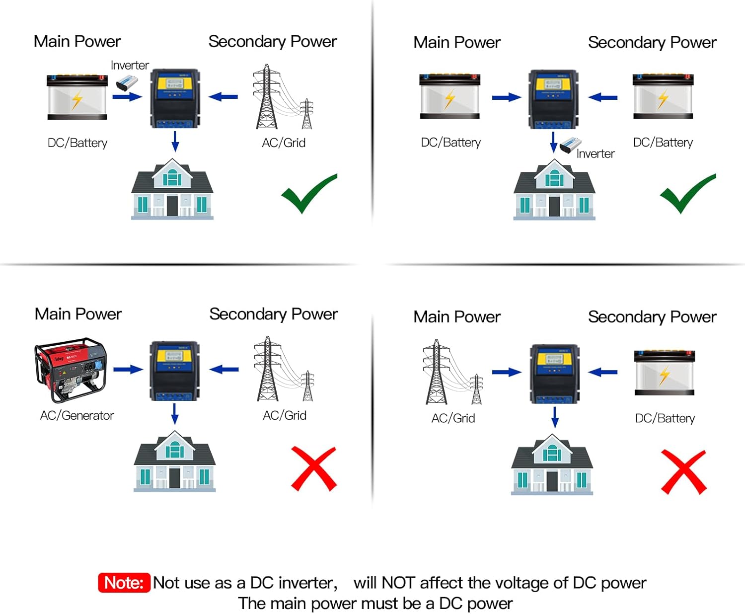
Figure 5: Correct and incorrect power configurations for the ATS. The main power source must be DC from the battery.
4.3. Mounting
Mount the ATS in a location that is:
- Protected from direct sunlight, moisture, and extreme temperatures.
- Well-ventilated to allow for heat dissipation.
- Easily accessible for wiring and monitoring.
5. Operating Instructions
Once installed, the MOES ATS operates largely automatically. The LCD display provides essential information for monitoring its status.
5.1. Automatic Transfer Logic
The ATS functions like an opposite-direction UPS, prioritizing battery power from your solar/wind system:
- Battery Power Priority: Under normal conditions, when your battery voltage is above the set recovery point, the ATS will draw power from your inverter (connected to the battery).
- Grid Power Transfer: If the battery voltage drops below the user-defined cut-off point (e.g., due to low solar/wind generation or high load), the ATS will automatically switch the load to the public grid power. This protects your batteries from deep discharge.
- Return to Battery Power: Once the battery voltage recovers and rises above the user-defined recovery point (e.g., after sufficient charging from solar/wind), the ATS will automatically switch the load back to the inverter (battery) power.

Figure 6: Product function diagram showing automatic transfer between public power and battery.
5.2. LCD Display and Settings
The LCD display shows critical information:
- BAT-V: Real-time battery voltage.
- Working Status Indicators: Icons indicating whether power is being drawn from the grid, inverter, or battery.
- Voltage Settings: The display allows you to view and adjust the cut-off and recovery voltages. Use the 'UP' and 'DOWN' buttons to navigate settings and 'ENTER' to confirm.
To adjust voltage settings:
- Press the 'MENU' button (if available, or a combination of UP/DOWN/ENTER as per specific model instructions) to enter the settings mode.
- Navigate to the 'Cut-Off Voltage' setting and adjust using 'UP'/'DOWN'.
- Navigate to the 'Recovery Voltage' setting and adjust using 'UP'/'DOWN'.
- Ensure the Recovery Voltage is always higher than the Cut-Off Voltage.
- Save settings (usually by pressing 'ENTER' or exiting the menu).
6. Maintenance
The MOES Dual Power Controller ATS is designed for low maintenance. However, regular checks can help ensure its longevity and reliable operation:
- Keep Clean: Periodically wipe the exterior of the unit with a dry, soft cloth to remove dust and debris. Do not use liquid cleaners.
- Check Connections: Annually, or if you notice any issues, visually inspect all wiring connections to ensure they are tight and free from corrosion. Loose connections can lead to overheating or intermittent operation.
- Ventilation: Ensure that the ventilation openings are not blocked to allow for proper airflow and prevent overheating.
- Environmental Conditions: Verify that the operating environment remains within the specified temperature and humidity ranges.
7. Troubleshooting
If you encounter issues with your MOES Dual Power Controller ATS, refer to the following troubleshooting guide:
| Problem | Possible Cause | Solution |
|---|---|---|
| ATS display is off / No power | No power from battery; Loose battery connection. | Ensure battery is charged. Check battery wiring connections to the ATS. The ATS is powered by the battery. |
| ATS not switching to grid power when battery is low | Incorrect cut-off voltage setting; No public grid power; Faulty connection. | Verify the cut-off voltage setting is appropriate for your battery type. Check if public grid power is available. Inspect 'Public Power' input wiring. |
| ATS not switching back to battery power when charged | Incorrect recovery voltage setting; Battery not fully charged to recovery level; Inverter issue. | Verify the recovery voltage setting. Ensure battery voltage has reached the recovery point. Check inverter operation and its connection to the ATS. |
| Slow or delayed transfer | Voltage fluctuations; Internal relay issue (rare). | Ensure stable input voltages. If problem persists, contact support. |
| Inaccurate battery voltage reading on LCD | Calibration needed. | Some units allow for voltage calibration. Refer to the specific product manual or contact support for instructions on how to adjust the offset (e.g., holding UP and DOWN buttons for 3 seconds). |
| Unit gets excessively hot | Overload; Poor ventilation; Loose connections. | Reduce the load on the ATS. Ensure adequate ventilation around the unit. Check all wiring connections for tightness. |
8. Warranty and Support
For detailed warranty information, please refer to the product documentation provided at the time of purchase or contact MOES customer support.
For further assistance, technical support, or to download the official User Guide in PDF format, please visit the MOES official website or refer to the following link:
When contacting support, please have your product model (NV-001) and any relevant purchase information ready.


