
1. Product Overview
The LIBO Stand-Alone Door Access Control System provides a secure and convenient solution for managing access to a single door. This comprehensive kit includes an access control keypad, a DC12V/3A power supply, an electric magnetic lock, a door exit release button, and 10 RFID EM ID keyfobs. The system supports multiple access methods including RFID card, password, or a combination of card and password, and can be fully programmed directly from the keypad without requiring a computer connection.
Included Components:
- 1 x Access Control Keypad
- 1 x Power Supply
- 1 x Electric Magnetic Lock
- 1 x Door Exit Button
- 10 x RFID Keyfobs
- 1 x User Manual (this document)
2. Component Details
2.1 Access Control Keypad (T22)

Image: Front view of the access control keypad, highlighting the Work Indicator, Card Area, Digital Buttons, and Door Bell Button/Enter key.
- Voltage: 12VDC
- Current: 120mA
- User Capacity: 1000 users
- Proximity Reader Frequency: 125KHz
- Compatible Cards: EM or EM compatible card
- Reading Distance: 3-10cm
- Access Modes: Card, password, Card + password
- Programming: Full programming from the keypad, stand-alone operation.
- Dimensions: 117 x 75 x 22mm
- Material: Plastic
2.2 Electric Magnetic Lock (180kg/350lbs)

Image: The electric magnetic lock, consisting of the main lock body and the armature plate, with wiring visible.
- Working Voltage: DC12V
- Working Current: 380-500mA
- Holding Force: 180kg (350lbs)
- Mode: NC (Fail-safe type - unlocked when power off, locked when power on)
- Features: Unfold install, Built-in voltage spike suppressor, waterproof, no LED working indicator light.
- Suitable For: Wooden doors, glass doors, metal doors, fireproof doors, etc.
- Dimensions: 170x23x39mm (main body) / 130x33x9.3mm (armature plate)
2.3 Power Supply (K80)
- AC Input: Standard AC100V-240V 50-60HZ 36W
- DC Output: DC12V/3A
- Outputs: NC / NO outputs for various electric locks.
- Protection: Automatic protection function against short circuits.
- Dimensions: 100x65x32mm
- Material: Metal
2.4 Door Exit Release Button
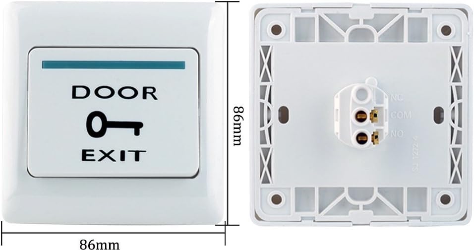
Image: Front and back view of the door exit button, showing its dimensions (86x86mm) and wiring terminals.
- Dimensions: 86x86x8mm
- Material: Fireproof ABS plastic
- Power Input: DC 12V
- Output Contact: NO / COM
2.5 RFID Keyfobs (10pcs)

Image: A set of 10 blue RFID keyfobs with metal keyrings, arranged in a pyramid shape.
- Frequency: 125KHz
- Type: EM ID
- Chip: TK4100
- Color: Blue
- Function: Read Only
- Quantity: 10 pieces
3. Specifications
| Feature | Detail |
|---|---|
| Brand | LIBO Smart Home |
| Model Number | T22-180kg |
| Power Source | DC |
| Voltage | 12 Volts |
| Connectivity Technology | Both Wired, Wireless |
| Sensor Technology | RFID |
| Control Method | Keypad |
| Installation Method | DIY |
| Item Dimensions (L x W x H) | 9 x 6 x 5 inches |
4. Setup & Installation
Proper installation and wiring are crucial for the correct functioning of the access control system. Refer to the wiring diagram below for connections between the access controller, power supply, magnetic lock, and exit button.
4.1 Wiring Diagram

Image: A detailed wiring diagram showing connections between the Power Supply, Access Controller, Magnetic Lock, and Exit Button. The Access Controller is connected to the Magnetic Lock and Exit Button, with the Power Supply providing power to the Access Controller.
4.2 Installation Example

Image: An illustrative diagram showing the access control keypad and magnetic lock installed on a wooden door, with the power supply and exit button also depicted in their typical installation locations.
General Installation Notes:
- Ensure all power is disconnected before beginning installation.
- Mount the access control keypad at a convenient height near the door.
- Install the magnetic lock securely on the door frame and the armature plate on the door, ensuring proper alignment for maximum holding force.
- Position the exit button on the inside of the door for easy egress.
- Follow local electrical codes and safety guidelines during wiring.
5. Operating Instructions
The access control keypad allows for various programming and access functions. The following sections detail common operations.
5.1 Keypad Operation Overview
The keypad features a work indicator, card area for RFID keyfobs, digital buttons (0-9), a door bell button (triangle symbol), and an enter button (hash symbol).
5.2 Programming and Access Functions
Watch the official product video below for a visual guide on how to operate the access control keypad, including setting passwords and managing cards.
Video: This video demonstrates the basic operation of the access control keypad, including how to set a public password, add new RFID cards, delete existing cards, and modify the program password. It shows the visual and auditory feedback from the keypad during these operations.
5.2.1 Setting Public Password
To set a public password, enter the following sequence on the keypad: # 123456 # 21 [New 4-digit Password] #. For example, to set the public password to 0987, you would enter: # 123456 # 21 0987 #.
5.2.2 Adding Cards
To add a new RFID card, enter the following sequence: # 123456 # 1 + [Card #] #. After entering the sequence, present the RFID card to the card area on the keypad. The keypad will provide an indication of successful card addition.
5.2.3 Deleting Cards
To delete an RFID card, use the sequence: # 123456 # 40 0000 #. This command is typically used to delete all cards. Refer to the full manual for specific card deletion methods if available.
5.2.4 Modifying Program Password
To change the program password (default is 123456), enter: # 123456 # 0 [New 6-digit Password] # [New 6-digit Password] #. For example, to change the program password to 456789, you would enter: # 123456 # 0 456789 # 456789 #.
6. Maintenance
To ensure the longevity and optimal performance of your LIBO Access Control System, follow these maintenance guidelines:
- Cleaning: Regularly wipe the keypad and other components with a soft, dry cloth. Avoid abrasive cleaners or solvents.
- Environmental Protection: Ensure the system components are protected from extreme temperatures, direct sunlight, and excessive moisture.
- Wiring Inspection: Periodically check all wiring connections for any signs of wear, corrosion, or looseness. Ensure connections are secure.
- Magnetic Lock: Keep the magnetic lock and armature plate clean and free of debris to maintain proper contact and holding force.
7. Troubleshooting
If you encounter issues with your access control system, refer to the following common problems and solutions:
- System Not Powering On: Check the power supply connections and ensure the power outlet is functional. Verify the DC12V/3A power supply is providing the correct voltage.
- Keypad Not Responding: Ensure the keypad is receiving power. Check for loose wiring connections to the access controller.
- RFID Card Not Working: Verify the card is compatible (125KHz EM ID type). Ensure the card has been properly added to the system. Try re-adding the card.
- Magnetic Lock Not Engaging/Disengaging: Check the wiring to the magnetic lock and the power supply. Ensure the NC/NO settings on the power supply are correct for your lock type. Verify the lock and armature plate are clean and aligned.
- Door Exit Button Not Working: Check the wiring connections for the exit button. Ensure the NO/COM contacts are correctly wired to the access controller.
- Incorrect Password Entry: Ensure you are entering the correct public or program password. If forgotten, refer to the manual for reset procedures (if available) or contact support.
8. Warranty and Support
For warranty information, technical support, or service inquiries, please refer to the documentation provided with your purchase or contact LIBO Smart Home customer service. Keep your purchase receipt as proof of purchase for warranty claims.