
Introduction
This manual provides detailed instructions for the installation, operation, and maintenance of your LIBO RFID Access Control System Kit. Please read this manual thoroughly before installation and use to ensure proper function and safety. This system is designed to provide secure access control for various applications.
Product Components
The LIBO RFID Access Control System Kit includes the following main components:
- Access Controller Keypad
- Electric Strike Lock (NC Type)
- DC12V/3A Power Supply
- Door Exit Button
- 10 RFID Key Fobs
Component Overview

Figure 1: Access Controller Keypad. This image shows the front of the access controller keypad, highlighting the Work Indicator, Card Area for RFID key fobs, Digital Buttons (0-9), Door Bell Button, and Enter button.

Figure 2: Electric Strike Lock (NC Type). This image displays the internal mechanism of the electric strike lock, featuring a full copper coil for continuous operation and an input voltage of DC 12V. This NC (Normally Closed) type lock provides strong applicability and enhanced security.
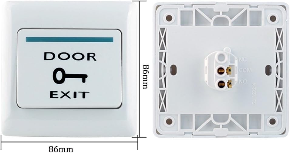
Figure 3: Door Exit Button. This image shows the front and rear views of the door exit button, indicating its dimensions of 86mm x 86mm. It features clear 'DOOR EXIT' labeling and connection terminals on the back.

Figure 4: RFID Key Fobs. A stack of 10 blue RFID key fobs (Model: ID-2#) made of ABS plastic. They operate at 125KHz low frequency, follow ISO 18000-2 protocol, and have a reading distance of 1-10cm. These are read-only key fobs.
Setup and Installation
Proper installation is crucial for the reliable operation of your access control system. It is recommended that installation be performed by a qualified technician.
Wiring Diagram
Follow the wiring diagram carefully to connect all components correctly. Incorrect wiring can damage the system or pose a safety risk.

Figure 5: Wiring Diagram. This diagram illustrates the connections between the Power Supply, Access Controller, Electric Strike Lock (NC Type), and Exit Button. Ensure all connections are secure and match the diagram.
Installation Steps
- Mount the Access Controller: Choose a suitable location near the door, typically at eye level. Securely mount the access controller keypad to the wall.
- Install the Electric Strike Lock: Integrate the electric strike lock into your door frame according to its specific mounting requirements. Ensure it aligns correctly with the door latch.
- Mount the Exit Button: Install the exit button on the inside of the door, allowing for easy egress.
- Connect Power Supply: Connect the DC12V/3A power supply to a suitable power outlet and then to the access control system as shown in the wiring diagram.
- Wire Components: Follow Figure 5 to connect the access controller, electric strike lock, and exit button to the power supply and each other. Pay close attention to positive/negative terminals and NC/NO connections for the lock.
- Test Connections: Before final assembly, perform a preliminary test to ensure all components are receiving power and responding correctly.

Figure 6: System Installation Overview. This image provides a visual representation of the complete access control system installed on a door, showing the Access Controller, Electric Strike Lock, Exit Button, and Power Supply in their typical positions.
Operating Instructions
Programming RFID Key Fobs
Refer to the specific programming instructions provided with your access controller for adding and removing RFID key fobs. Typically, this involves entering a master code, selecting a programming mode, and then presenting the key fobs to the card area.
Accessing the Door
- Using an RFID Key Fob: Present a programmed RFID key fob to the 'Card Area' on the access controller. The work indicator will change, and the electric lock will disengage for a set period.
- Using the Keypad: Enter a valid access code using the digital buttons and press the 'Enter' button. The electric lock will disengage.
- Exiting the Door: Press the 'DOOR EXIT' button from the inside to disengage the electric lock and open the door.
Maintenance
- Regular Cleaning: Keep the access controller keypad and RFID card area clean and free from dust and debris using a soft, dry cloth.
- Check Wiring: Periodically inspect all wiring connections for any signs of wear, corrosion, or looseness. Ensure all connections remain secure.
- Lock Mechanism: Ensure the electric strike lock mechanism operates smoothly. Lubricate moving parts if necessary, using a non-conductive lubricant.
- Power Supply: Verify the power supply is functioning correctly and providing stable DC12V output.
Troubleshooting
- System Not Powering On:
- Check if the power supply is plugged in and receiving power.
- Verify all power connections according to the wiring diagram.
- Ensure the power supply is outputting 12V DC.
- Door Lock Not Engaging/Disengaging:
- Confirm the electric strike lock is correctly wired (NC type).
- Check for obstructions in the lock mechanism.
- Ensure the access controller is sending the correct signal.
- RFID Key Fobs Not Working:
- Ensure the key fobs are correctly programmed into the access controller.
- Present the key fob firmly and correctly to the 'Card Area'.
- Check for any interference near the card reader.
- Exit Button Not Working:
- Verify the exit button is correctly wired to the access controller.
- Check for any damage to the button itself.
Specifications
| Feature | Detail |
|---|---|
| Brand | LIBO Smart Home |
| Model Number | T22-YJS |
| Part Number | Access Control Kit 06 |
| UPC | 192687566211 |
| Color | Gray, Black |
| Power Source | Electric (DC12V / 3A) |
| Voltage | 12 Volts |
| Connectivity Technology | Wired |
| Control Method | Keypad, RFID, Push Button (for exit) |
| RFID Key Fob Frequency | 125KHz low frequency |
| RFID Key Fob Protocol | ISO 18000-2 |
| RFID Key Fob Reading Distance | 1-10 cm |
| Item Weight | 1.16 Kilograms (Package Weight) |
| Package Dimensions (L x W x H) | 12.9 x 18.2 x 23.5 cm |
| Installation Type | Designed for fixed installation |
| Alert Type | Audio only, Motion only (System alerts) |
| Country of Origin | China |
Warranty Information
LIBO Smart Home products are typically covered by a limited manufacturer's warranty. Please refer to the warranty card included with your product or visit the official LIBO Smart Home website for detailed warranty terms and conditions. Keep your purchase receipt as proof of purchase for any warranty claims.
Support
For technical assistance, troubleshooting, or further inquiries regarding your LIBO RFID Access Control System Kit, please contact LIBO Smart Home customer support. Contact information can usually be found on the product packaging or the official LIBO Smart Home website.
Online Resources: For additional guides and FAQs, please visit the LIBO Smart Home support page.