1. Introduction
This manual provides detailed instructions for the installation, operation, and maintenance of the TOAUTO F21-E1B Wireless Crane Remote Control System. This system is designed for industrial applications requiring reliable wireless control of hoists and cranes. Please read this manual thoroughly before operating the device to ensure safe and efficient use.
2. Product Overview
The TOAUTO F21-E1B system consists of two transmitters and one receiver, providing robust wireless control for various industrial lifting equipment.

Figure 2.1: The TOAUTO F21-E1B system, showing the receiver unit on the left and two handheld transmitter units on the right. The receiver is orange with a wiring diagram label, and the transmitters are also orange with multiple control buttons.
2.1. Transmitter Features
- Number of Function Buttons: 6 x one-step buttons (Up/Down, East/West, South/North).
- Additional Buttons: 1 START button, 1 STOP button.
- Material: Glass-Fiber PA.
- Protection Class: IP65.
- Safety Code: 32 bits (4.3 billion combinations).
- Battery Indicator: LED on the front indicates battery condition (green for sufficient, red for low).
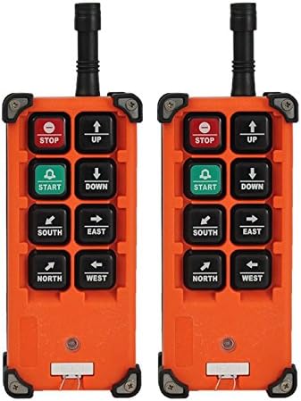
Figure 2.2: Two handheld transmitter units. Each transmitter features a red STOP button, a green START button, and six directional buttons (Up, Down, East, West, South, North).

Figure 2.3: An exploded view of a transmitter, showing the outer casing, the button panel, the circuit board with button contacts, and the internal battery compartment.
2.2. Receiver Features
- Power Supply: 12V AC/DC.
- Material: Glass-Fiber PA.
- Protection Class: IP65.
- Safety Code: 32 bits (4.3 billion combinations).
- Cable Length: 1.65 meters.

Figure 2.4: A partial internal view of the receiver unit, showing the circuit board with various electronic components and wiring connections within the orange casing.

Figure 2.5: An exploded view of the receiver unit, displaying the external casing, the internal circuit board with relays, and the cable gland for wiring connections.
3. Specifications
3.1. Transmitter Specifications
| Parameter | Value |
|---|---|
| Dimension | 164 x 75 x 46 mm |
| Weight (without batteries) | 315 G |
| Frequency Range | VHF: 310~331MHz; UHF: 425~446MHz |
| Transmitter Power | ≤ 10dBm |
| Temperature Range | -40~85 degrees Celsius (-40~185 degrees Fahrenheit) |
| Control Distance | Approx. 100m (200 meters customizable) |
3.2. Receiver Specifications
| Parameter | Value |
|---|---|
| Power Supply | 12V AC/DC |
| Dimension | 205 x 86 x 80 mm |
| Weight | 620 G |
| Frequency Range | VHF: 310~331MHz; UHF: 425~446MHz |
| Receiver Sensitivity | -110dBm |
| Temperature Range | -40~85 degrees Celsius (-40~185 degrees Fahrenheit) |
| Control Distance | Approx. 100m (200 meters customizable) |
4. Setup and Installation
4.1. Receiver Wiring
Connect the receiver to the crane or hoist control system according to the wiring diagram provided. Ensure the power supply matches the receiver's requirement of 12V AC/DC. Proper grounding is essential for safe operation.
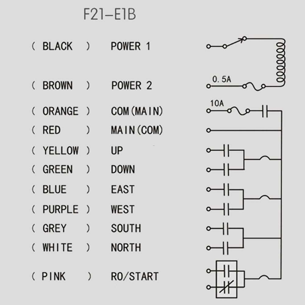
Figure 4.1: Wiring diagram for the F21-E1B receiver. It illustrates connections for Power 1 (Black), Power 2 (Brown), COM/MAIN (Orange/Red), and directional controls (Yellow for UP, Green for DOWN, Blue for EAST, Purple for WEST, Grey for SOUTH, White for NORTH), along with RO/START (Pink).
4.2. Transmitter Battery Installation
The transmitters require AA alkaline batteries (not included). To install, open the battery compartment on the back of the transmitter and insert the batteries, observing correct polarity. Close the compartment securely.
5. Operating Instructions
5.1. Basic Operation
- Ensure the receiver is powered on and correctly wired to the crane/hoist system.
- Press the START button on the transmitter to activate the control system.
- Use the directional buttons (UP, DOWN, EAST, WEST, SOUTH, NORTH) to control the movement of the crane or hoist. These buttons can be programmed for interlock or non-interlock operation.
- To stop operations, press the large red STOP button.
5.2. Battery Indicator
The LED on the front of the transmitter indicates the battery status:
- Flashing Green: Battery power is sufficient for operation.
- Flashing Red: Battery power is low. Replace both batteries promptly.
6. Maintenance
6.1. Battery Replacement
When the transmitter's LED flashes red, or if operation becomes erratic or range decreases, replace both AA alkaline batteries with new ones. Always replace both batteries simultaneously to ensure consistent performance.
6.2. Cleaning
Clean the exterior of the transmitter and receiver with a soft, damp cloth. Do not use abrasive cleaners or solvents. Ensure the devices are dry before use.
7. Troubleshooting
7.1. No Response from Transmitter
- Check the transmitter's battery indicator. If flashing red, replace batteries.
- Ensure the receiver is powered on and its power indicator is active.
- Verify that the transmitter and receiver are within the specified control distance (approx. 100m).
- Check for any physical obstructions or strong electromagnetic interference between the transmitter and receiver.
7.2. Erratic Operation or Reduced Range
- Replace the transmitter batteries, even if the LED is not yet solid red.
- Ensure there are no new sources of radio frequency interference in the operating environment.
8. Application
The TOAUTO F21-E1B Wireless Crane Remote Control System is suitable for a variety of industrial applications, including but not limited to:
- Bridge Cranes
- Overhead Cranes
- Chain Hoists
- Monorails
- Concrete Pump Trucks
- Mobile Lifting Equipment
- Tower Cranes
9. Package Contents
The TOAUTO F21-E1B package includes the following items:
- 2 x Transmitter Units
- 1 x Receiver Unit
- 1 x Dust Bag
- 1 x User Manual (this document)
10. Warranty and Support
For warranty information, technical support, or service inquiries, please contact your TOAUTO product supplier or visit the official TOAUTO website. Keep your purchase receipt for warranty claims.


