
Introduction
This manual provides detailed instructions for the installation, operation, and maintenance of your LIBO Smart Home Electric Drop Bolt Lock, Model L-XXS. This electronic lock is designed for access control security systems, featuring a fail-safe NC (Normally Closed) mode and adjustable time delay. Please read this manual thoroughly before installation and use to ensure proper function and safety.
Safety Information
- Ensure the power supply is disconnected before any installation or maintenance procedures.
- This device operates on DC 12V. Using an incorrect voltage may damage the unit.
- Installation should be performed by qualified personnel if you are unfamiliar with electrical wiring.
- Do not attempt to modify or disassemble the lock beyond what is described in this manual.
- Keep the device away from water and excessive humidity.
Package Contents
Verify that all components are present in the package:
- 1 x LIBO Smart Home Electric Drop Bolt Lock (Model L-XXS)
- 1 x Bag of Installation Kit (screws, etc.)

Image: The Electric Drop Bolt Lock and its installation kit, shown with its packaging.
Specifications
| Model Name | L-XXS |
| Dimensions (L x W x H) | 150 x 34 x 28 mm (5.91 x 1.34 x 1.1 inches) |
| Lock Core Diameter | 12.5 mm (0.49 inches) |
| Lock Core Extension Length | 15 mm (0.59 inches) |
| Working Voltage | DC 12V |
| Starting Current | 1.2A |
| Persistent Current | 120mA |
| Operating Mode | NC (Normally Closed) - Locked when powered, unlocked when power is off (Fail-Safe) |
| Time Delay | Adjustable: 0s, 3s, 6s |
| Material | Aluminum Alloy |
| Suitable Door Types | Wooden door, Glass door, Metal door, Fireproof door |
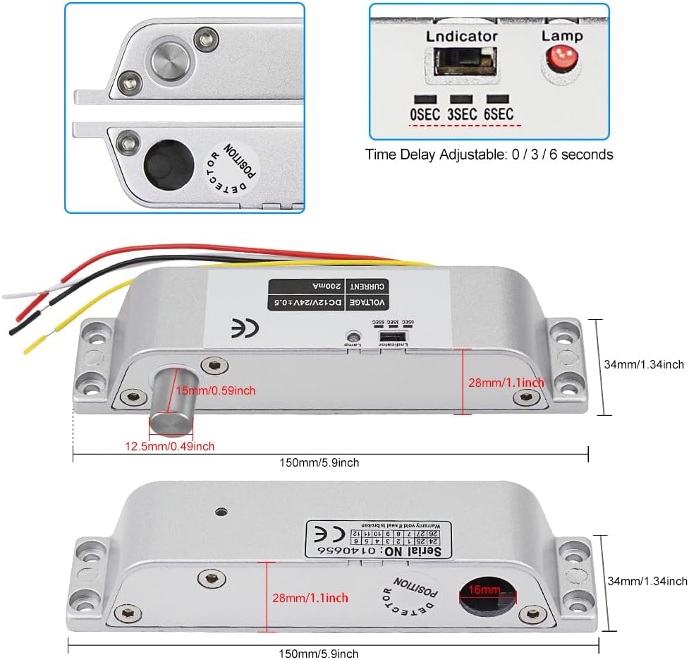
Image: Detailed view of the lock showing dimensions, wiring, and time delay switch.
Setup and Installation
The LIBO Smart Home Electric Drop Bolt Lock is designed for unfold (surface mounted) installation. It consists of two main parts: the lock body and the strike plate (receiver).
Installation Steps:
- Choose Installation Location: Determine whether to install the lock on the top or side of the door frame. Ensure the lock body and strike plate align perfectly when the door is closed.
- Marking: With the door closed, position the lock body and strike plate on the door frame and door edge respectively. Mark the screw holes and the position for the lock bolt.
- Drilling: Drill pilot holes for the mounting screws. For the lock bolt, ensure the hole in the door frame is deep enough to accommodate the 15mm bolt extension.
- Mounting: Securely attach the lock body to the door frame and the strike plate to the door using the provided screws. Ensure both parts are flush and stable. The lock body uses hexagon screws for enhanced security.
- Wiring: Refer to the "Wiring Diagram" section for proper electrical connections.
- Testing: After wiring, test the lock's functionality before fully securing all covers or finishing the installation.
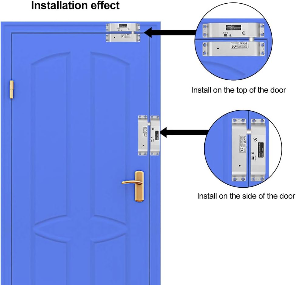
Image: Visual examples demonstrating installation on the top and side of a door.

Image: A top-down view showing the lock body and the strike plate, highlighting the bolt and detector positions.
Wiring Diagram
The Electric Drop Bolt Lock requires a DC 12V power supply. Follow the wiring instructions carefully:
- Red Wire: Connect to the NC (Normally Closed) terminal of your access control system or positive (+) terminal of the DC 12V power supply.
- Black Wire: Connect to the GND (Ground) terminal of your access control system or negative (-) terminal of the DC 12V power supply.
- Yellow and White Wires: These wires are for door status feedback (reed switch). They do not carry voltage and act as a relay contact. They are typically used to signal if the door is closed, but not necessarily locked. If not needed for your system, they can be left unconnected.
Important: Ensure correct polarity when connecting the power supply to avoid damage to the lock.
Operating Instructions
The LIBO Smart Home Electric Drop Bolt Lock operates in NC (Normally Closed) mode, meaning it is locked when power is supplied and unlocks when power is removed (fail-safe). The lock engages when the door is closed and the strike plate's magnet activates the internal reed switch, signaling the lock to extend its bolt.
Time Delay Adjustment:
The lock features an adjustable time delay for unlocking. This can be useful for coordinating with door closers or other access control components. The delay can be set to 0 seconds, 3 seconds, or 6 seconds using the switch located on the side of the lock body.
- 0s: No delay. The lock unlocks immediately when power is cut.
- 3s: 3-second delay. The lock unlocks 3 seconds after power is cut.
- 6s: 6-second delay. The lock unlocks 6 seconds after power is cut.
Adjust the switch to your desired delay setting. The green LED on the lock will blink according to the set delay after the door closes and the bolt engages.
Maintenance
The LIBO Smart Home Electric Drop Bolt Lock is designed for durability and requires minimal maintenance. To ensure optimal performance:
- Regularly inspect the lock and strike plate for any signs of wear, damage, or misalignment.
- Keep the lock bolt and the strike plate's receiving hole free from dust and debris. A clean, dry cloth can be used for cleaning.
- Do not apply lubricants unless specifically recommended by the manufacturer, as some lubricants can attract dirt.
- Ensure all mounting screws remain tight.
Troubleshooting
| Problem | Possible Cause | Solution |
|---|---|---|
| Lock does not engage (bolt does not extend). |
|
|
| Lock does not disengage (bolt remains extended). |
|
|
| Lock engages but retracts immediately or cycles. |
|
|
Warranty and Support
For warranty information or technical support, please refer to the documentation provided at the point of purchase or contact LIBO Smart Home customer service. Keep your purchase receipt as proof of purchase.