1. Product Overview
The Teletek CA62 is a sophisticated 12-zone control panel designed for security systems in homes, medium-sized commercial premises, and offices. It offers robust security management through various external control devices, including the compact and user-friendly LED62 keypad.
The system is expandable and supports up to 12 zones (5 on-board + 1 keypad zone), allowing for comprehensive coverage. It features a built-in digital communicator and supports common communication protocols like Contact ID and SIA for central monitoring. The CA62 control panel is designed for professional hard-wired installation and operates on AC power with battery backup for continuous protection.
2. System Components and Setup
The Teletek CA62 system includes the main control panel, an LED62 keypad, a plastic housing box, and a power supply transformer. A 12V / 7Ah battery is required but not included and must be sourced separately to ensure uninterrupted operation during power outages.

Figure 2.1: External view of the Teletek CA62 control panel casing. This white, rectangular enclosure protects the internal components of the alarm system.
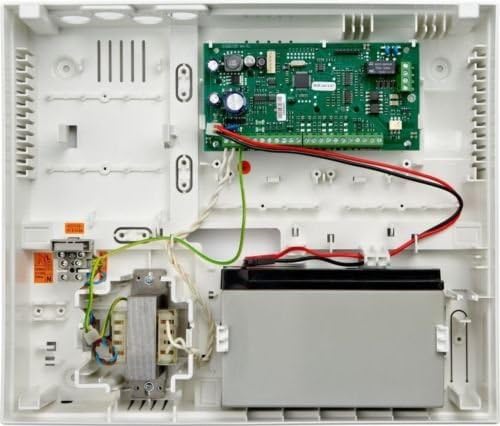
Figure 2.2: Internal view of the Teletek CA62 control panel. This image shows the main circuit board, wiring connections, transformer, and the designated space for the backup battery.
2.1. Installation Guidelines
The CA62 system is designed for professional hard-wired installation. Ensure all wiring is done according to local electrical codes and manufacturer specifications. The system supports up to 4 devices connected to its bus. Proper balancing resistors are required for zone connections (1/2 balancing resistors; doubling zone connection).
Power Connection: Connect the 230V/17 VAC / 17 VA mains transformer to the control panel. Install a 12V / 7Ah battery in the designated compartment for backup power. The power output is 13.8 V / 1A, protected by a resettable fuse.
Keypad Connection: Connect the LED62 keypad to the control panel. The keypad can be located up to 500 meters from the panel.
Zone Wiring: Wire your security zones (e.g., door contacts, motion sensors) to the appropriate terminals on the control panel. The system supports up to 12 zones.
3. Operating Instructions
The LED62 keypad provides an easy and comfortable interface for operating your security system. Security management can also be achieved via an LCD keypad (optional), a proximity cards reader (optional), a pulse switch, or remote programming software.

Figure 3.1: Close-up of the Teletek LED62 keypad's display and top function buttons. The display shows system status and zone indicators (1-12), along with arming mode indicators (A, B).

Figure 3.2: Full view of the Teletek LED62 keypad with the numeric pad revealed. This shows all buttons for system control, including quick arming shortcuts and dedicated emergency buttons.
3.1. Keypad Features
- Shortcut Buttons: For quick arming of the system.
- Emergency Buttons: Three dedicated buttons for sending FIRE, MEDICAL, and PANIC alarm messages to a central monitoring station.
- LED Indication: Provides clear status updates for the system, individual zones, and current arming modes.
- Programming Mode: A guide is available within the programming mode to assist with system configuration.
- Tamper Switch: Bi-directional TAMPER switch for enhanced security.
3.2. Basic Operations
- Arming the System: Enter your user code or use the quick arming shortcut buttons (e.g., 'A' or 'B' buttons for specific partitions/modes). The LED indicators will confirm the armed status.
- Disarming the System: Enter your user code when prompted. The system status LEDs will change to indicate disarmed status.
- Sending Emergency Signals: In an emergency, press and hold the dedicated FIRE, MEDICAL, or PANIC buttons for a few seconds to send an immediate alarm to the monitoring station.
- Checking System Status: Observe the LED indicators on the keypad for zone status (open/closed), system armed/disarmed status, and any fault conditions.
The system supports 20 user codes, 4 manager codes, and 1 engineer code. It maintains a memory of 256 events with data and time stamps.
4. Maintenance
Regular maintenance ensures the optimal performance and longevity of your Teletek security system.
- Battery Check: Periodically check the 12V / 7Ah backup battery. While the system operates on AC power, the battery provides crucial power during outages. Replace the battery as needed, typically every 3-5 years, or if the system indicates a low battery fault.
- Cleaning: Gently wipe the keypad and control panel casing with a soft, dry cloth. Avoid using abrasive cleaners or solvents.
- System Testing: Conduct periodic tests of your alarm system, including all zones and emergency buttons, to ensure they are functioning correctly. Inform your monitoring station before conducting tests to avoid false alarms.
- Wiring Inspection: For professional installations, it is recommended to have a qualified technician inspect wiring connections periodically to ensure they remain secure and free from damage.
5. Troubleshooting
If you encounter issues with your Teletek security system, consider the following basic troubleshooting steps:
- No Power: Check the main AC power supply and ensure the transformer is properly connected. Verify the backup battery is installed and charged.
- Keypad Not Responding: Ensure the keypad is securely connected to the control panel. Check for any visible damage to the keypad or its cable.
- Zone Faults: If a zone indicates a fault, check the associated sensor (e.g., door/window contact, motion detector) to ensure it is closed or clear. Inspect the wiring for that zone for any breaks or loose connections.
- False Alarms: Review recent events in the system's memory (256 events stored with data and time) to identify patterns. Ensure sensors are properly installed and not triggered by environmental factors or pets.
For complex issues or if the problem persists, it is recommended to contact a qualified security system technician or Teletek customer support for assistance.
6. Specifications
| Feature | Detail |
|---|---|
| Model Number | CA62 |
| Manufacturer | Teletek |
| Number of Zones | Up to 12 (5 on board + 1 keypad zone) |
| Zone Balancing | 1/2 balancing resistors; doubling zone connection |
| Number of Outputs | 3 low current + 1 high current |
| Number of Codes | 20 users, 4 manager, 1 engineer |
| Memory of Events | 256 events with data and time |
| Digital Communicator | Built-in, TBR-21 approved |
| Communication Protocols | Contact ID, SIA |
| Programming | By keypad, ProSTE Software (Optional) |
| Bus Devices | Up to 4 devices connected to the system bus |
| Mains Transformer | 230V/17 VAC / 17 VA |
| Battery (Not Included) | 12 V / 7 Ah |
| Power Output | 13.8 V / 1A, Resettable fuse protected |
| Current Consumption | 100 mA (Control Panel) |
| Operating Temperature (Control Panel) | 0°C / +40°C |
| Housing | ABS plastic box |
| Dimensions (Control Panel) | 335 x 290 x 105 mm |
| Keypad Power Supply (LED62) | 12 V DC from the panel |
| Keypad Current Consumption (LED62) | 50-150 mA |
| Keypad Operating Temperature (LED62) | -5°C / +40°C |
| Keypad Storage Temperature (LED62) | -20°C / +60°C |
| Keypad Distance to Panel (LED62) | Up to 500 m |
| Power Source | AC Power with Battery Backup |
| Compatible Devices | Smartphone (via optional software/modules) |
| Connectivity Technology | Wired |
| Installation Type | Professional hard-wired |
| Alert Type | Motion & Entry & Fire & Medical & Panic |
| Voltage | 12 Volts |
| Control Method | Touch (Keypad) |
| Included Components | Control panel CA62, LED keypad LED62, Plastic box, Power supply transformer |
| Date First Available | June 17 2018 |
| UPC | 702188347457 |
7. Warranty and Support
For specific warranty information regarding your Teletek Security Alarm System, please refer to the documentation provided at the time of purchase or contact Teletek directly. Warranty terms and conditions are typically provided by the manufacturer.
For technical support, installation assistance, or any questions regarding the operation of your CA62 control panel or LED62 keypad, please reach out to Teletek customer support or your authorized installer. Professional assistance is recommended for complex system configurations or troubleshooting.