1. Introduction
The MikroTik CRS112-8P-4S-IN is a Cloud Router Switch designed for network environments requiring advanced management capabilities and Power over Ethernet (PoE) functionality. This device features eight Gigabit Ethernet ports with PoE-out capabilities and four SFP ports for fiber optic connectivity. It operates on MikroTik's RouterOS Level 5, providing extensive configuration options for routing, switching, and network management.
This manual provides essential information for the proper installation, operation, maintenance, and troubleshooting of your CRS112-8P-4S-IN switch.
2. Safety Information
- Always disconnect power before cleaning or servicing the device.
- Ensure proper ventilation to prevent overheating. Do not block ventilation openings.
- Use only the power adapter supplied with the device or a compatible power supply that meets the specified voltage and current requirements.
- Avoid exposing the device to water, moisture, or extreme temperatures.
- This device is intended for indoor use only.
- Installation should be performed by qualified personnel in accordance with local electrical codes.
3. Package Contents
Verify that your package contains the following items:
- MikroTik CRS112-8P-4S-IN Smart Switch unit
- Power Adapter (typically 24V, 2.5A)
- Power Cord
- Rackmount ears (optional, may be included or sold separately)
- Mounting screws (if rackmount ears are included)

Figure 3.1: Front view of the CRS112-8P-4S-IN Smart Switch.
4. Hardware Overview
The CRS112-8P-4S-IN features a compact design with various ports and indicators for network connectivity and status monitoring.
4.1 Front Panel
- 8 x Gigabit Ethernet Ports: RJ45 ports supporting 10/100/1000 Mbps speeds with PoE-out capabilities.
- 4 x SFP Ports: For 1 Gbps fiber optic uplinks.
- LED Indicators: Power, User, and Ethernet port status LEDs.
4.2 Rear Panel
- DC Input Jacks: Two DC input jacks. One supports 18-28V DC, and the other supports 48-57V DC.
- Grounding Screw: For connecting a grounding wire.
- Reset Button: For resetting the device to factory defaults or entering RouterBOOT loader.
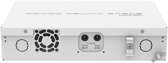
Figure 4.1: Rear view of the CRS112-8P-4S-IN Smart Switch showing DC input jacks.
5. Setup
Follow these steps to set up your MikroTik CRS112-8P-4S-IN switch.
5.1 Connecting Power
- Connect the provided power cord to the power adapter.
- Connect the power adapter's output plug to one of the DC input jacks on the rear panel of the switch. The switch supports 18-28V DC or 48-57V DC.
- Plug the power cord into a suitable electrical outlet. The device will power on automatically.

Figure 5.1: Included power adapter.

Figure 5.2: Power cord.
Note on PoE: For 802.3af/at PoE/PoE+ output, a 48-57V DC power supply is required. If using the standard 18-28V DC power supply, only Passive PoE is available, and the maximum current per port is 1A. With a 48-57V DC supply, the maximum current per port is 450mA.
5.2 Connecting Network Cables
- Connect your network devices (computers, servers, access points) to the Gigabit Ethernet ports (RJ45) on the front panel.
- If using fiber optic connections, insert compatible SFP modules into the SFP ports and connect fiber optic cables.
5.3 Initial Configuration Access
The CRS112-8P-4S-IN runs RouterOS. Initial configuration can be performed via:
- WinBox: A graphical utility for Windows. Download from the MikroTik website.
- WebFig: A web-based interface accessible via a web browser.
- Serial Console: For advanced users, via a serial cable (not included).
By default, the device will attempt to obtain an IP address via DHCP. If no DHCP server is present, it will typically default to 192.168.88.1. Refer to the MikroTik documentation for detailed RouterOS configuration guides.
6. Operating
Once powered on and connected, the CRS112-8P-4S-IN functions as a managed switch and router. Its operation is primarily controlled through the RouterOS software.
6.1 Basic Switching and PoE
- The Ethernet ports will automatically detect connected devices and establish network links.
- PoE-out ports will automatically detect and provide power to compatible PoE devices (802.3af/at or Passive PoE) based on the connected power supply.
6.2 RouterOS Functionality
RouterOS allows for advanced network configurations, including:
- VLAN management
- Firewall rules
- Routing protocols
- Quality of Service (QoS)
- Link aggregation
- Monitoring and diagnostics
Detailed instructions for these features are available in the MikroTik RouterOS documentation on their official website.
7. Maintenance
Regular maintenance ensures optimal performance and longevity of your device.
7.1 Cleaning
- Periodically clean the exterior of the device with a soft, dry cloth.
- Ensure ventilation openings are free from dust and debris. Do not use liquid cleaners or aerosols.
7.2 Firmware Updates
It is recommended to keep RouterOS firmware updated to the latest stable version to benefit from new features, performance improvements, and security patches. Firmware updates can be performed via WinBox or WebFig. Always back up your configuration before performing a firmware update.
8. Troubleshooting
This section addresses common issues you might encounter.
8.1 No Power
- Check if the power cord is securely connected to both the device and the electrical outlet.
- Verify that the power adapter is functioning correctly.
- Ensure the electrical outlet is live.
8.2 No Network Connectivity
- Check the Ethernet cable connections. Ensure they are securely plugged into both the switch and the connected device.
- Verify the link/activity LEDs on the switch ports. If they are off, there might be a cable issue or the connected device is not powered on.
- Confirm IP address settings on your connected devices and the switch.
8.3 PoE Not Working as Expected
- Ensure you are using a 48-57V DC power supply for 802.3af/at PoE/PoE+ devices. The included 24V power supply only supports Passive PoE.
- Check the power requirements of the connected PoE device.
- Verify PoE settings within RouterOS for the specific ports.
8.4 SFP Port Issues
- Ensure compatible SFP modules are used.
- If experiencing connectivity issues, try manually setting the SFP port speed to 1Gbps within RouterOS, disabling auto-negotiation.
8.5 Resetting to Factory Defaults
To reset the device to its factory default configuration:
- With the device powered on, press and hold the reset button located on the rear panel.
- Continue holding the button until the user LED starts flashing.
- Release the button to reset the device.
9. Specifications
| Feature | Specification |
|---|---|
| Model | CRS112-8P-4S-IN |
| Ethernet Ports | 8 x 10/100/1000 Mbps RJ45 with PoE-out |
| SFP Ports | 4 x 1 Gbps SFP |
| PoE Output | Passive PoE (18-28V DC input), 802.3af/at (48-57V DC input) |
| Max Current per PoE Port | 1A (18-28V input), 450mA (48-57V input) |
| Data Transfer Rate | 1000 Megabits Per Second |
| Operating System | RouterOS Level 5 |
| Dimensions | Refer to product datasheet |
| Weight | Approximately 2 pounds (0.9 kg) |
| Operating Temperature | Refer to product datasheet (up to 60 Degrees Celsius) |
| Power Input | 18-28V DC or 48-57V DC |
10. Warranty and Support
MikroTik products typically come with a limited manufacturer's warranty. For specific warranty terms and conditions, please refer to the documentation provided with your purchase or visit the official MikroTik website. Technical support, additional documentation, and software downloads are available through the MikroTik support portal: mikrotik.com/support.
It is recommended to register your product on the MikroTik website for access to the latest resources and support.