1. Introduction
This manual provides comprehensive instructions for the safe and effective use of your Cloudray MYJG-50W CO2 Laser Power Supply. Please read this manual thoroughly before installation and operation to ensure optimal performance and longevity of your equipment.
The Cloudray MYJG-50W power supply is designed for 50W CO2 laser tubes, offering fast response, high performance, and features to extend laser tube lifespan. It is suitable for various laser engraving and cutting applications.
2. Safety Information
WARNING: Untrained personnel operation is prohibited. This device generates high voltage and laser radiation. Failure to follow safety instructions can result in serious injury or death.
- Always ensure proper grounding of the power supply and laser system.
- Do not operate the power supply without a connected laser tube and proper cooling system.
- Ensure adequate ventilation to prevent overheating.
- Disconnect power before performing any maintenance or wiring changes.
- Wear appropriate personal protective equipment (PPE), including laser safety glasses, when working with laser systems.
- Keep children and unauthorized personnel away from the laser equipment.
3. Product Overview
The Cloudray MYJG-50W CO2 Laser Power Supply is a robust unit designed for stable and efficient power delivery to 50W CO2 laser tubes. It features advanced control and protection mechanisms.
3.1 Key Features
- Good compatibility with 50W laser tubes from various manufacturers.
- Fast response speed and high performance for efficient cutting.
- TTL level control for easy laser start and stop.
- Open circuit output protection to prevent damage to the power supply.
- Integrated indicators for TTL signal, water protection, and laser output.
- Manual test buttons for laser output verification.
- External ammeter port for current display and adjustment.
3.2 Components and Connections

Figure 3.2.1: Front view of the Cloudray MYJG-50W CO2 Laser Power Supply. This image shows the main body of the power supply with ventilation grilles and the front panel displaying the model number and safety warnings.

Figure 3.2.2: Rear view of the Cloudray MYJG-50W CO2 Laser Power Supply. This image highlights the input and output terminals, including the AC input, high voltage output, and control signal ports.

Figure 3.2.3: Detailed wiring diagram showing all connection points on the Cloudray MYJG-50W power supply. Labels indicate connections for high voltage output, AC input (115V/230V optional), test button, water protection, signal ground, input control signal (0-5V), output power 5V, and laser signal input.

Figure 3.2.4: Close-up view of key components including the product label, input/output ports, external ammeter display, and internal cooling fan. This image provides a visual guide to the main functional parts of the power supply.
4. Setup and Installation
Proper installation is critical for the safe and efficient operation of your laser system. Refer to Figure 3.2.3 for wiring details.
- Mounting: Securely mount the power supply in a well-ventilated area, ensuring adequate space for airflow around the unit. Refer to the dimensions diagram (Figure 4.1.1) for mounting hole locations.
- Grounding: Connect the FG (Frame Ground) terminal to a reliable earth ground. This is essential for safety.
- AC Input: Connect the AC input (L and N) to your mains power supply. The unit supports both 115V and 230V AC. Ensure the correct voltage is selected if there is a switch, or that your unit is compatible with your local voltage.
- High Voltage Output: Connect the high voltage output (LASER terminal) to the anode of your CO2 laser tube. Connect the cathode of the laser tube to the return path of your laser system. Exercise extreme caution as this is a high voltage connection.
- Control Signals:
- Water Protection (WP): Connect your water flow switch or sensor to the water protection input. The power supply will prevent laser firing if water flow is not detected.
- TTL Control (H/L): Connect your laser controller's TTL signal to the appropriate H (active high) or L (active low) input for laser ON/OFF control.
- Input Control Signal (0-5V): Connect your analog control signal (0-5V) to this input to adjust laser power output.
- Signal Ground (G): Connect the ground reference for your control signals.
- Output Power 5V (5V): Provides a 5V output for external devices if needed.
- External Ammeter (Optional): Connect the provided external ammeter to the dedicated port (P and L) for real-time current monitoring. Refer to Figure 4.1.2 for connection details.
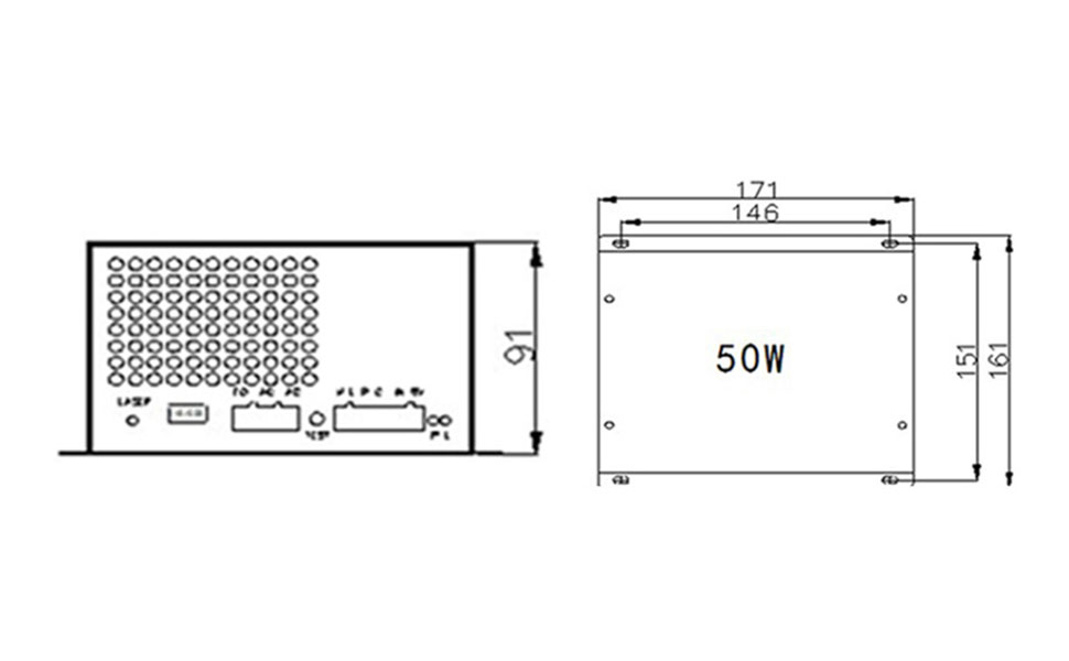
Figure 4.1.1: Dimensions diagram of the Cloudray MYJG-50W power supply, showing length, width, and height in millimeters, along with mounting hole positions. This is crucial for planning installation space.

Figure 4.1.2: The Cloudray MYJG-50W power supply connected to its external ammeter. This image also highlights the internal switch (L/R) which determines if the current adjustment knob on the ammeter is active (R position) or if power is solely controlled by the 6-pin terminal input (L position).
5. Operating Instructions
Once installed, the power supply is ready for operation. Always ensure all safety precautions are observed.
- Power On: Connect the power supply to the mains. The internal fan should start, indicating power is supplied.
- Water Protection Check: Ensure your water cooling system is functioning correctly. The water protection indicator on the power supply or external ammeter should show "ON". The laser will not fire without proper water flow.
- Laser Control: Use your laser controller to send TTL signals to the power supply to enable or disable the laser output.
- Power Adjustment:
- External Ammeter Control: If the switch on the power supply (refer to Figure 4.1.2) is in the right (R) position, the current adjustment knob on the external ammeter can be used to fine-tune the laser output current.
- External Signal Control: If the switch is in the left (L) position (default), the laser output power is determined solely by the 0-5V analog input signal from your laser controller.
- Test Button: The "TEST" button on the power supply allows for a momentary laser output for testing purposes. Use with extreme caution and only when the laser path is clear and safe.
- Monitoring: Observe the external ammeter for real-time laser current readings. This helps in maintaining optimal laser performance and preventing tube damage from overcurrent.
6. Maintenance
Regular maintenance ensures the longevity and reliable operation of your Cloudray MYJG-50W power supply.
- Cleaning: Periodically clean the ventilation grilles and fan to prevent dust buildup, which can impede cooling and lead to overheating. Use compressed air or a soft brush.
- Connections: Regularly check all wiring connections to ensure they are secure and free from corrosion. Loose connections can cause intermittent operation or damage.
- Environment: Ensure the operating environment remains within the specified temperature and humidity ranges to prevent component degradation.
- Cooling System: Verify that your laser's water cooling system is functioning correctly and providing adequate cooling to the laser tube. A faulty cooling system can lead to power supply and laser tube damage.
7. Troubleshooting
This section provides solutions to common issues you might encounter.
| Problem | Possible Cause | Solution |
|---|---|---|
| No laser output |
|
|
| Low laser power |
|
|
| Power supply overheating |
|
|
| Ammeter not displaying current |
|
|
8. Specifications
Technical specifications for the Cloudray MYJG-50W CO2 Laser Power Supply.
| Parameter | Value |
|---|---|
| Model Number | MYJG-50W |
| Input Voltage | AC115V / AC230V (selectable/auto-sensing) |
| AC Frequency | 47 - 440Hz |
| Max Output Voltage | 22KV |
| Max Output Current | 22mA |
| Output Power | 50 Watts |
| Dimensions (L x W x H) | 171mm x 161mm x 91mm |
| Weight | 1.5 kg |
| Efficiency | 91% |
| MTBF (Mean Time Between Failures) | ≥ 30000 hours |
| Response Speed | ≤ 1Ms |
| Voltage Range (High-Level) | ≥ 3V |
| Voltage Range (Low-Level) | ≤ 0.7V |
| Operating Environment Temperature | -30°C to +65°C |
| Cooling Method | Forced air cooling (fan cooling) |
| High Temperature Test | Full Load / 60°C / 12 hours |
| Start / Stop Test Cycles | 500 times 7 seconds |
| UPC | 669819726817 |

Figure 8.1.1: A detailed table outlining the technical specifications of the Cloudray M50 (MYJG-50W) laser power supply, including input/output parameters, dimensions, weight, efficiency, and environmental conditions.
9. Warranty and Support
Cloudray products are manufactured to high standards. For warranty information and technical support, please refer to the official Cloudray website or contact your authorized dealer. Keep your purchase receipt for warranty claims.
For further assistance, you may visit the Cloudray Brand Store on Amazon.


