1. Introduction
This manual provides essential instructions for the safe and effective installation, operation, and maintenance of your Walfront Pressure Switch. Please read this manual thoroughly before using the product and retain it for future reference.
2. Safety Information
Always observe the following safety precautions to prevent injury or damage to the product:
- Ensure the air compressor system is depressurized and disconnected from power before installation or maintenance.
- Wear appropriate personal protective equipment (PPE), such as safety glasses.
- Installation should be performed by qualified personnel familiar with air compressor systems and electrical connections.
- Do not exceed the specified pressure range of 120-150 PSI.
- Verify all connections are secure and leak-free before restoring pressure and power.
3. Product Overview
The Walfront Pressure Switch is designed to control the operation of an air compressor by sensing the system pressure. It automatically turns the compressor ON when pressure drops to 120 PSI and OFF when it reaches 150 PSI.
Key Features:
- Durable metal housing construction.
- Pre-set pressure range: ON at 120 PSI, OFF at 150 PSI.
- 1/8 NPT threaded connector for easy integration.
- Normally Open contact type.

Figure 3.1: Front view of the Walfront Pressure Switch, showing the label with ON/OFF pressure settings.
4. Setup and Installation
Follow these steps for proper installation of the pressure switch:
- Depressurize System: Ensure the air compressor system is completely depressurized and disconnected from its power source.
- Locate Mounting Point: Identify the appropriate 1/8 NPT threaded port on your air compressor or manifold for the pressure switch.
- Apply Thread Sealant: Apply a suitable thread sealant (e.g., PTFE tape or pipe dope) to the threads of the pressure switch to ensure an airtight seal.
- Install Switch: Carefully thread the pressure switch into the designated port. Tighten securely with a wrench, but do not overtighten to avoid damaging the threads or the switch housing.
- Electrical Connections: Connect the electrical terminals of the pressure switch to the compressor's control circuit. This switch features a Normally Open contact type, meaning the circuit is closed (compressor ON) when pressure is below 120 PSI and open (compressor OFF) when pressure reaches 150 PSI. Refer to your compressor's wiring diagram for specific connections.
- Verify Connections: Double-check all pneumatic and electrical connections for security and correctness.

Figure 4.1: Detailed views of the pressure switch, highlighting the threaded connector and electrical terminals for installation reference.
5. Operating Instructions
Once installed, the pressure switch operates automatically:
- Restore Power: Reconnect the air compressor to its power source.
- Initial Operation: The compressor will start automatically if the system pressure is below 120 PSI.
- Automatic Cycling: The compressor will continue to run until the system pressure reaches 150 PSI, at which point the pressure switch will open the circuit and turn the compressor OFF.
- Pressure Drop: When air is used and the system pressure drops to 120 PSI, the pressure switch will close the circuit, turning the compressor ON again to replenish the air supply.
Monitor the compressor's first few cycles to ensure it operates within the specified pressure range and cycles correctly.
6. Maintenance
The Walfront Pressure Switch is designed for durability and requires minimal maintenance. However, regular checks are recommended:
- Visual Inspection: Periodically inspect the switch for any signs of physical damage, corrosion, or loose connections.
- Leak Checks: Check for air leaks around the threaded connection point. If a leak is detected, depressurize the system and re-tighten the switch or reapply thread sealant.
- Functionality Test: Observe the compressor's cycling to ensure the switch is activating and deactivating at the correct pressure points (120 PSI ON, 150 PSI OFF).
Always ensure the system is depressurized and power is disconnected before performing any maintenance.
7. Troubleshooting
If you encounter issues with your pressure switch, refer to the following table:
| Problem | Possible Cause | Solution |
|---|---|---|
| Compressor does not turn ON. |
|
|
| Compressor does not turn OFF. |
|
|
| Air leak at switch connection. |
|
|
8. Specifications
| Feature | Detail |
|---|---|
| Model | B07BXG82TF |
| Brand | Walfront |
| Pressure Range | ON at 120 PSI, OFF at 150 PSI |
| Connector Type | 1/8 NPT Threaded |
| Operation Mode | ON-OFF |
| Contact Type | Normally Open |
| Circuit Type | 1-way |
| Mounting Type | Flush Mount |
| Actuator Type | Diaphragm |
| Contact Material | Metal |
| Product Dimensions (L x W x H) | 3.54 x 2.36 x 2.36 inches |
| Weight | 0.71 ounces |
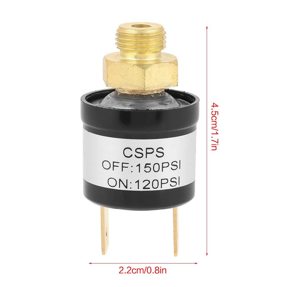
Figure 8.1: Walfront Pressure Switch with key dimensions indicated.
9. Warranty and Support
For warranty information or technical support regarding your Walfront Pressure Switch, please refer to the documentation provided with your purchase or contact Walfront customer service directly. Contact details can typically be found on the product packaging or the official Walfront website.
