1. Introduction
This manual provides essential instructions for the safe and effective use of the TOAUTO Industrial Radio Remote Control system. This wireless control system is designed for operating cranes and similar industrial equipment, offering enhanced flexibility and safety. Please read this manual thoroughly before installation and operation.

Image 1.1: The TOAUTO Industrial Radio Remote Control system, showing both the handheld transmitter and the receiver unit.
2. Package Contents
Verify that all items listed below are present in your package:
- One Transmitter unit with hanging belt
- One Dust Bag
- One Receiver unit
- One 1.65m connection cable for the receiver
- One Operation and Maintenance Manual (this document)

Image 2.1: The TOAUTO remote control system components as packaged, including the transmitter, receiver, and cables.
3. Specifications
3.1 General Technical Specifications
| Feature | Specification |
|---|---|
| Control Distance | Approx. 100m (200m customizable) |
| Material | Glass-Fiber PA |
| Operation Frequency | 310.0325-331.165 MHz |
| Certificates | CE, FCC |
| Unique ID Codes | Over 4.3 billion |
| Working Temperature | -40°C to +85°C |
3.2 Transmitter Specifications (Model F21-TX)
| Feature | Specification |
|---|---|
| Dimensions | 156 x 61 x 51 mm |
| Weight | 255g |
| Enclosure Protection Class | IP65 |
| Transmitter Power | ≤10dBm |
| Power Supply | 2 AA batteries |
| Safety Code | 32 bits (4.3 billion) |
3.3 Receiver Specifications (Model F21-RXC)
| Feature | Specification |
|---|---|
| Dimensions | 205 x 86 x 80 mm |
| Weight | 620g |
| Enclosure Protection Class | IP65 |
| Frequency Range | VHF: 310-331MHz; UHF: 425-446MHz |
| Receiver Sensitivity | -110dBm |
| Receiver Power Supply | 18-65V AC/DC; 65-440V AC/DC (Optional) |
| Output Contactor Capacity | 8A sealed relay output (with AC 250V/10A relays, 10A fuse) |
| Cable Length | 1.65 meters |
| Safety Code | 32 bits (4.3 billion) |

Image 3.1: A visual representation of the transmitter and receiver specifications, including dimensions and technical parameters.
4. Setup
4.1 Receiver Wiring
The receiver unit requires proper electrical connection to the crane or industrial equipment. Refer to the wiring diagram below for correct terminal connections. Ensure all connections are secure and comply with local electrical codes.

Image 4.1: Wiring diagram for the F21-E1/E2 receiver, detailing connections for power and control signals (e.g., UP, DOWN, EAST, WEST, NORTH, SOUTH, RO/START).
4.2 Power Supply Connection
The receiver supports a wide range of AC/DC power inputs. Ensure the power supply connected matches the receiver's specifications (18-65V AC/DC or 65-440V AC/DC). The system features a switching power supply for high conversion efficiency.

Image 4.2: Illustration of the receiver's power supply options (AC/DC 65V-440V and AC/DC 18V-65V) and the damping rubber mounting for vibration reduction.
4.3 Transmitter Battery Installation
The transmitter requires two AA batteries (not included). To install or replace batteries, locate the battery cabin on the transmitter. The design allows for easy disassembly. Ensure correct polarity when inserting batteries.
Image 4.3: Diagram showing the easy disassembly of the transmitter's battery cabin for battery replacement and access to the data cable terminal for programming.
5. Operation
5.1 Power On/Off and Safety
To power on the transmitter, use the safety key switch. This prevents unauthorized use. The transmitter features a red mushroom head emergency stop button for immediate power cut-off in critical situations. Some models include a rotary key for enhanced safety.
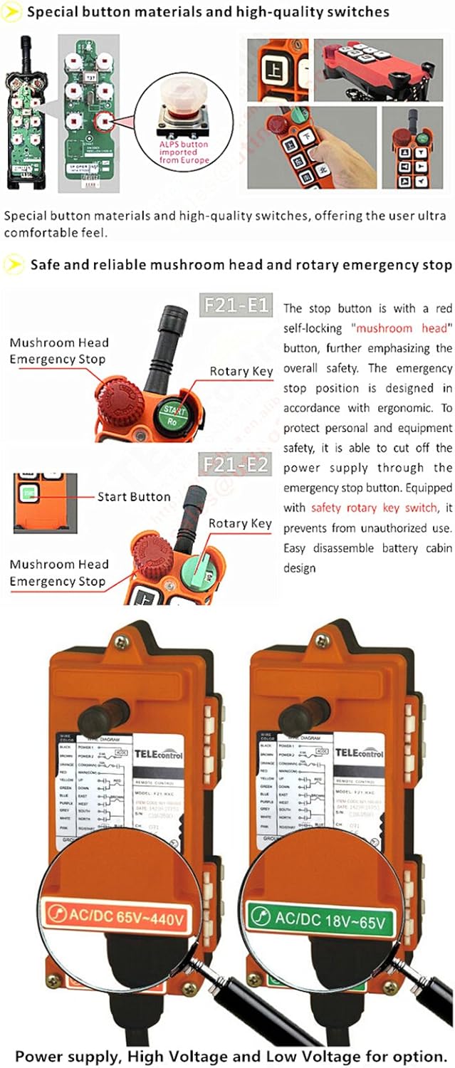
Image 5.1: Close-up of the transmitter's safety features, including the mushroom head emergency stop button and the rotary key switch (F21-E1 and F21-E2 models shown).
5.2 Button Functions
The transmitter is equipped with 7 operation buttons: 6 single-speed directional buttons (Up, Down, East, West, North, South) and one 'STOP' button. A 'START' button is also present. These buttons control the corresponding functions of the connected equipment.
- Directional Buttons: Control movement (Up/Down, East/West, North/South). These can be configured for mutual inhibition (preventing simultaneous opposite movements) or independent operation via computer interface.
- START Button: Initiates operation.
- STOP Button: Halts all operations immediately.
- Spare Key: Can be programmed for various functions such as acceleration, toggle switch, or other specific operations.
5.3 Battery Voltage Warning
The transmitter includes an LED indicator that signals the operating state. During low power conditions, the LED will blink to alert the user to replace batteries. The system will enter a protective mode if power becomes critically low.
Image 5.2: The LED indicator on the transmitter, which provides visual feedback on the operating status and warns of low battery power.
6. Key Features
- Durable Construction: Made from Glass-Fiber PA material, not standard plastic, for enhanced durability.
- High-Quality Buttons: Utilizes German-imported buttons for reliable and comfortable operation.
- Extended Service Life: Equipped with high-quality relays to prolong the operational life of the remote control system.
- Secure Cabling: The receiver's connection cable is designed for safety and strength.
- Laser-Marked Labels: Important information such as Serial Number (S/N) and Channel (CH) is laser-marked to prevent loss and ensure traceability, even in harsh environments.
- Configurable Functions: Internal functions can be set via a computer interface, allowing customization of button behavior and interlock settings.
- Vibration Damping: The receiver features damping rubber mounting screws to reduce the impact of vibration during operation.
Image 6.1: Example of laser-engraved labels on both the transmitter and receiver, ensuring important identification information remains clear and legible.
7. Maintenance
Regular maintenance ensures the longevity and reliable operation of your TOAUTO Industrial Radio Remote Control system.
- Cleaning: Keep both the transmitter and receiver units clean and free from dust and debris. Use a soft, dry cloth. Avoid harsh chemicals.
- Battery Replacement: Replace transmitter batteries promptly when the low power warning indicator blinks. Always use new AA batteries.
- Cable Inspection: Periodically inspect the receiver's connection cable for any signs of wear, damage, or fraying. Replace if necessary.
- Label Integrity: Ensure the laser-marked labels on both units remain legible. These contain critical information for service and identification.
- Damping Rubber: Check the damping rubber mounting on the receiver for any signs of degradation. This helps absorb vibrations and protects the internal components.
8. Troubleshooting
This section addresses common issues you might encounter with your remote control system.
- No Response from Equipment:
- Check if the transmitter is powered on and batteries are not low.
- Ensure the receiver has power and is correctly wired.
- Verify that the safety key switch on the transmitter is in the 'ON' position.
- Confirm that the transmitter and receiver are within the operational control distance (approx. 100m).
- Check for potential radio interference in the operating environment.
- Transmitter LED Blinking:
- This indicates low battery power. Replace the AA batteries in the transmitter immediately.
- Intermittent Control:
- Could be due to weak batteries, environmental interference, or being at the edge of the control range.
- Inspect receiver wiring for loose connections.
- Emergency Stop Not Functioning:
- Immediately cease operation. Inspect the emergency stop button for physical damage. Do not use the system until this critical safety feature is fully functional.
If issues persist after following these steps, contact customer support.
9. Warranty and Support
For warranty information, please refer to the documentation provided at the time of purchase. For technical support, service, or spare parts, please contact TOAUTO customer service through your retailer or the official TOAUTO channels.


