1. Introduction
Thank you for choosing the SP Tools 3-48V Circuit Tester, Model SP61012. This device is designed for safely testing electrical circuits in automotive and truck applications, providing accurate voltage readings and polarity indications. This manual provides essential information for the proper and safe operation, maintenance, and troubleshooting of your circuit tester. Please read this manual thoroughly before use and retain it for future reference.
2. Safety Instructions
Always observe the following safety precautions to prevent injury or damage to the circuit tester or the vehicle's electrical system.
- Voltage Range: This tester is designed for circuits between 3V and 48V DC. Do not use it on AC circuits or circuits exceeding 48V, as this may damage the tool or cause electric shock.
- Insulation: Ensure your hands are dry and you are standing on a dry surface when using the tester. Avoid contact with live circuits with bare hands.
- Eye Protection: Always wear appropriate eye protection (safety glasses or goggles) when working with vehicle electrical systems.
- Vehicle Battery: Disconnect the vehicle's battery if instructed by the vehicle manufacturer's service manual for specific procedures.
- Circuit Overload: Do not intentionally short circuit the vehicle's electrical system. The tester is designed to draw minimal current (Imax 12 mA) for safe testing.
- Damaged Tool: Do not use the circuit tester if it appears damaged or if the cable insulation is compromised.
- Professional Use: If you are unsure about any electrical procedure, consult a qualified automotive technician.
3. Product Overview
The SP Tools 3-48V Circuit Tester consists of a main probe unit with an integrated LED indicator and a ground clip connected via a flexible cable.
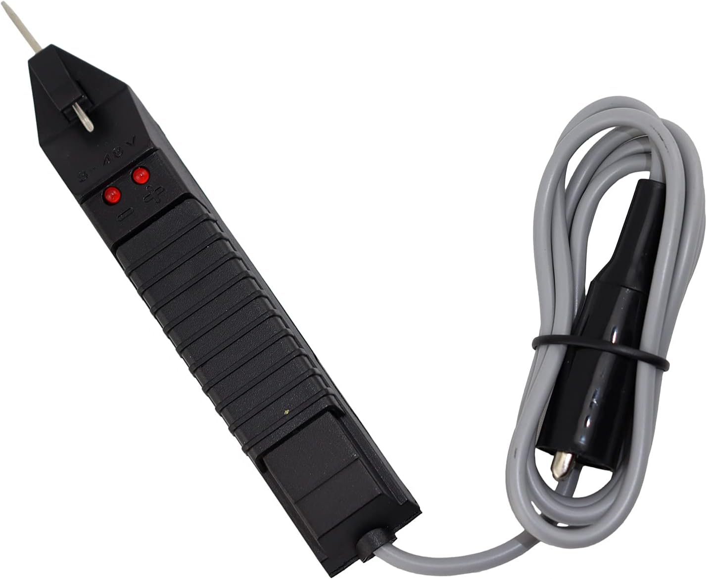
Figure 3.1: Front view of the SP Tools 3-48V Circuit Tester.

Figure 3.2: Back view of the SP Tools 3-48V Circuit Tester, showing specifications.
Components:
- Probe Tip: Sharp, pointed metal tip for piercing wire insulation or contacting terminals.
- Main Body: Ergonomic handle containing the internal circuitry and LED indicators.
- LED Indicators: Two LEDs (typically red) that illuminate to indicate voltage presence and polarity. One LED for positive, one for negative.
- Cable: Insulated electrical cable connecting the main body to the ground clip.
- Alligator Clip: Spring-loaded clip for securely attaching to a ground point (e.g., vehicle chassis or battery negative terminal).
4. Setup
- Prepare the Vehicle: Ensure the vehicle's ignition is off unless the test specifically requires power.
- Connect Ground: Securely attach the alligator clip of the circuit tester to a known good ground point on the vehicle chassis or the negative terminal of the vehicle's battery. A clean, unpainted metal surface is ideal for a good connection.
- Verify Connection (Optional but Recommended): Briefly touch the probe tip to the positive terminal of the vehicle's battery. The positive LED on the tester should illuminate, confirming a good ground connection.
5. Operating Instructions
The SP Tools 3-48V Circuit Tester is used to check for voltage presence and polarity in DC circuits.
- Identify Test Point: Locate the wire or terminal you wish to test.
- Apply Probe: Carefully touch the sharp probe tip to the circuit point. You may need to gently pierce the wire insulation if testing a covered wire.
- Observe LED Indicators:
- If the positive LED illuminates, the circuit point has a positive voltage (e.g., +12V).
- If the negative LED illuminates, the circuit point has a negative voltage or is a ground connection.
- If neither LED illuminates, there is no voltage present at that point, or the voltage is outside the 3-48V range, or there is an open circuit.
- If both LEDs illuminate, this indicates an AC voltage or a fault in the circuit. This tester is designed for DC circuits.
- Interpret Results: Use the LED indications to diagnose the circuit. For example, if a fuse is blown, the circuit might show no voltage on one side of the fuse, but voltage on the other.
- Remove Probe: Once testing is complete, carefully remove the probe tip from the circuit.
Note: The tester draws a small current (maximum 12 mA) when connected, which is safe for most automotive electronic circuits. However, always refer to the vehicle's service manual for specific testing procedures and precautions.
6. Maintenance
The SP Tools 3-48V Circuit Tester requires minimal maintenance.
- Cleaning: Wipe the tester with a clean, dry cloth after each use. Do not use abrasive cleaners or solvents.
- Storage: Store the tester in a dry, cool place, away from direct sunlight and extreme temperatures. Keep the probe tip protected to prevent accidental damage or injury.
- Inspection: Periodically inspect the cable for cuts, cracks, or frayed insulation. Check the alligator clip for secure attachment and corrosion. Do not use the tester if any damage is observed.
7. Troubleshooting
| Problem | Possible Cause | Solution |
|---|---|---|
| No LEDs illuminate when testing a known live circuit. |
|
|
| Only one LED illuminates when expecting both (e.g., on an AC circuit). | Tester is designed for DC circuits only. | Do not use this tester on AC circuits. Use an appropriate AC voltage tester or multimeter. |
| LEDs flicker or are dim. |
|
|
8. Specifications
- Model Number: SP61012
- Brand: SP Tools
- Voltage Range: 3 - 48 Volts DC
- Maximum Current Draw: 12 mA
- Power Source: Hand-powered (draws power from circuit being tested)
- LED Indicator: Yes, for polarity indication (positive/negative)
- Dimensions (Product): Approximately 25 x 20 x 8 cm (L x W x H)
- Weight (Product): Approximately 250 g
- Included Components: 1 x Circuit Tester
9. Warranty and Support
SP Tools products are manufactured to high-quality standards. For information regarding warranty coverage, technical support, or service, please refer to the warranty card included with your product or visit the official SP Tools website.
Website: www.sptools.com (Please note: This is a general example, actual website may vary by region.)


