1. Introduction
This manual provides comprehensive instructions for the installation, operation, maintenance, and troubleshooting of the Delta DVP08XM211N DVP-ES2 I/O Module. This module is designed as an 8-point digital input extension for Delta DVP-ES2 series PLCs, providing reliable and efficient signal acquisition for industrial automation applications.
Please read this manual thoroughly before operating the device to ensure proper usage and to prevent damage or injury.
2. Safety Information
Always adhere to the following safety precautions to ensure safe operation and to prevent damage to the module or connected equipment:
- Ensure power is disconnected before installation, wiring, or maintenance.
- Only qualified personnel should perform installation and wiring.
- Verify all wiring connections are correct and secure before applying power.
- Do not expose the module to excessive moisture, dust, or corrosive environments.
- Operate the module within its specified environmental and electrical ratings.
3. Package Contents
Upon opening the package, verify that all items listed below are present and undamaged:
- Delta DVP08XM211N DVP-ES2 I/O Module (1 unit)
- Quick Start Guide (1 copy)
4. Product Overview
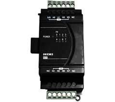
Figure 4.1: Front view of the Delta DVP08XM211N DVP-ES2 I/O Module. This image shows the terminal blocks for input connections, power indicators, and model labeling.
The DVP08XM211N is an expansion module designed to extend the digital input capabilities of Delta DVP-ES2 series Programmable Logic Controllers (PLCs). It features 8 digital input points, allowing for the connection of various sensors and switches to the PLC system. The module is compact and designed for DIN rail mounting, integrating seamlessly into industrial control panels.
4.1. Components and Indicators
- Input Terminals (X0-X7): Screw terminals for connecting digital input signals.
- Power Indicator (POWER): LED that illuminates when the module receives power.
- Input Status Indicators (0-7): LEDs corresponding to each input point (X0-X7), illuminating when the respective input is active.
- Communication Port: For connection to the main PLC unit.
5. Setup and Installation
5.1. Mounting
The DVP08XM211N module is designed for DIN rail mounting. To mount:
- Hook the top groove of the module onto the DIN rail.
- Push the bottom of the module firmly until it clicks into place.
- Ensure the module is securely fastened to prevent vibration.
5.2. Wiring
Before wiring, ensure all power sources are disconnected. Refer to the PLC's manual for specific wiring diagrams for expansion modules. General wiring guidelines are as follows:
- Power Supply: Connect the appropriate DC power supply to the module's power terminals. Observe polarity.
- Input Connections: Connect your digital input devices (e.g., limit switches, proximity sensors) to the X0-X7 input terminals. Ensure common (COM) connections are correctly wired.
- Communication Cable: Connect the module to the main DVP-ES2 series PLC using the dedicated communication cable or connector provided with the PLC system.
Note: Incorrect wiring can damage the module or connected equipment. Always double-check connections before applying power.
6. Operating Instructions
Once the module is correctly installed and wired, power can be applied to the PLC system. The DVP08XM211N module will automatically be recognized by the DVP-ES2 series PLC.
6.1. Indicator Lights
- POWER LED:
- ON: Module is powered on and operating normally.
- OFF: No power or power supply issue.
- Input Status LEDs (0-7):
- ON: The corresponding digital input (X0-X7) is active (e.g., sensor detected, switch closed).
- OFF: The corresponding digital input is inactive.
6.2. Programming
The digital input states from the DVP08XM211N module can be accessed and utilized within the PLC program using the PLC's programming software (e.g., ISPSoft). Refer to the DVP-ES2 series PLC programming manual for details on addressing and using expansion module inputs.
7. Maintenance
The DVP08XM211N module is designed for low maintenance. However, regular checks can ensure optimal performance and longevity:
- Cleaning: Periodically clean the module's exterior with a soft, dry cloth. Do not use solvents or abrasive cleaners.
- Connection Check: Routinely inspect wiring connections for looseness or corrosion. Tighten terminals as necessary.
- Environmental Check: Ensure the operating environment remains within specified temperature and humidity ranges, and free from excessive dust or vibration.
8. Troubleshooting
If you encounter issues with the DVP08XM211N module, refer to the following common problems and solutions:
| Problem | Possible Cause | Solution |
|---|---|---|
| POWER LED is OFF | No power supply or incorrect wiring. | Check power connections and ensure the power supply is active and within specifications. |
| Input Status LED (e.g., X0) is OFF when input is active | Incorrect input wiring, faulty sensor, or module communication issue. | Verify input device functionality. Check wiring to the input terminal. Ensure communication cable to PLC is secure. |
| Module not recognized by PLC | Loose communication cable, incompatible PLC firmware, or faulty module. | Ensure communication cable is securely connected. Check PLC firmware compatibility. If issues persist, contact technical support. |
9. Specifications
| Parameter | Value |
|---|---|
| Model | DVP08XM211N |
| Type | Digital Input Expansion Module |
| Input Points | 8 (Sink/Source selectable) |
| Input Voltage | 24 VDC |
| Compatibility | Delta DVP-ES2 Series PLCs |
| Mounting | DIN Rail |
| Dimensions (Approx.) | Refer to product datasheet for exact dimensions. |
| Operating Temperature | 0°C to 55°C (32°F to 131°F) |
| Storage Temperature | -25°C to 70°C (-13°F to 158°F) |
| Humidity | 35% to 85% RH (non-condensing) |
10. Warranty and Support
10.1. Warranty Information
Delta products are typically covered by a limited warranty against defects in materials and workmanship. The specific warranty period and terms may vary by region and product. Please refer to the warranty card included with your product or visit the official Delta website for detailed warranty information.
Note: The warranty does not cover damage caused by improper installation, misuse, unauthorized modification, or operation outside of specified environmental conditions.
10.2. Technical Support
For technical assistance, troubleshooting beyond this manual, or inquiries regarding product functionality, please contact Delta's authorized technical support or your local distributor. Have your product model number (DVP08XM211N) and serial number ready when contacting support.
You can find contact information for Delta's global offices and support channels on their official website: www.deltaww.com


