Introduction
This manual provides comprehensive instructions for the installation, operation, and maintenance of your Wolf Guard LB-01A 110dB Standalone Siren Basic Security Burglar Alarm System. Please read this manual carefully before use to ensure proper functionality and safety.
The Wolf Guard LB-01A system is designed to provide basic security for various locations such as cabins, carports, build sites, sheds, and porches. It features a loud 110dB siren and a high-brightness flash to deter intruders. The system operates as a standalone unit and can be expanded with additional sensors.
Package Contents
Upon opening the package, verify that all components listed below are present and in good condition:
- 1 x Wolf Guard LB-01A Siren Unit (Main Panel)
- 1 x Motion Detector (PIR Sensor HW-03D)
- 2 x Key Fob Remotes
- 2 x Door/Window Sensors (MC-03B)
- 1 x DC 12V 500mA Power Adapter
- 1 x User Manual (this document)
- 1 x Quick Installation Guide
- Required mounting hardware (screws, wall plugs)

Figure 1: Unboxed components of the Wolf Guard LB-01A alarm system. This image displays the main siren unit, a passive infrared (PIR) motion detector, two remote key fobs, two magnetic door/window sensors, the DC 12V power adapter, and various instruction manuals and mounting accessories.
Setup and Installation
1. Powering the Siren Unit
The main siren unit can be powered either by the included DC 12V 500mA adapter or by four 1.5V LR20 batteries (not included, but recommended for backup power during outages). For optimal performance and continuous operation, it is recommended to use both the adapter and batteries.
- Connect the DC 12V 500mA power adapter to the siren unit's power input port.
- Plug the adapter into a standard electrical outlet.
- For battery backup, open the battery compartment on the back of the siren unit and insert four 1.5V LR20 batteries, ensuring correct polarity.

Figure 2: Rear view of the siren unit, illustrating the mounting bracket and the power input port. This view also shows the internal fan and various certification marks.
2. Installing the Motion Detector (PIR Sensor)
The PIR sensor detects movement within its detection area. It is powered by four AAA 1.5V dry batteries (included).
- Open the battery compartment of the PIR sensor and insert four AAA 1.5V batteries, observing polarity.
- Locate the small switch inside the PIR sensor's battery compartment or on its circuit board. Ensure this switch is in the "ON" position.
- Mount the PIR sensor on a wall at a height of approximately 1.8 to 2.2 meters (5.9 to 7.2 feet) from the floor. Avoid direct sunlight, heat sources, or areas with strong air currents.
- The detection range is up to 12 meters with a horizontal angle of 110° and a vertical angle of 60°. Position the sensor to cover the desired area without obstructions.

Figure 3: Illustration of the PIR sensor's optimal mounting height (1.8-2.2m) and its detection coverage, showing a 100-degree side view and a 10-meter range.
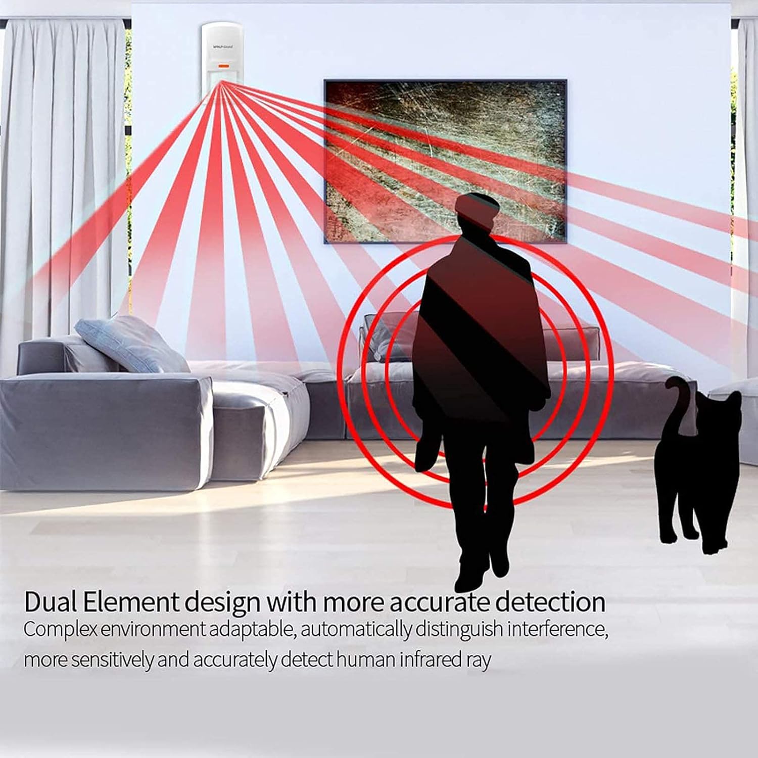
Figure 4: The PIR sensor's "Dual Element design" is depicted, highlighting its ability to accurately detect human infrared rays while adapting to complex environments and distinguishing interference, as shown with a person and a pet.
3. Installing the Door/Window Sensors
The door/window sensors consist of two parts: a main transmitter unit and a magnetic stripe. They are powered by a built-in CR2032 lithium battery with an average life of 2 years.
- Identify the main transmitter unit (larger part) and the magnetic stripe (smaller part).
- Locate the small switch on the bottom of the main transmitter unit. Ensure it is in the "ON" position.
- Peel the adhesive backing from both parts.
- Attach the main transmitter unit to the door or window frame, and the magnetic stripe to the moving part of the door or window.
- Ensure the small magnetic stripe is aligned with the marked area on the main transmitter unit when the door/window is closed. The gap between the two parts should be less than 10mm when closed.

Figure 5: A door/window sensor is shown installed on a window frame. The image illustrates how the sensor's two parts separate when the window is opened, triggering an alarm.
4. Pairing Sensors (Pre-configured)
The included sensors are pre-configured with the siren unit from the factory. No manual pairing is typically required for initial setup. If you purchase additional sensors (up to 99pcs), refer to the quick installation guide for pairing instructions.
Operating the System
Key Fob Remote Functions
The key fob remotes provide convenient control over the alarm system:
- LOCK Button (🔒): Press this button to arm the system. The siren unit will indicate that the system is armed (e.g., a single beep or LED change). Once armed, any triggered sensor will activate the alarm.
- UNLOCK Button (🔓): Press this button to disarm the system or to turn off an active alarm sound. The siren unit will indicate that the system is disarmed.
- SOS Button (SOS): Press this button to immediately trigger the alarm, regardless of the system's armed status. This is for emergency situations.
- Home Mode Button (🏠): This button may activate a "home" or "stay" mode, where certain sensors (e.g., perimeter sensors like door/window contacts) are armed while internal sensors (like PIR) are disarmed, allowing movement within the protected area. Refer to the quick guide for specific functionality.
Alarm Triggering
When the system is armed, an alarm will be triggered under the following conditions:
- The motion detector senses movement within its detection zone.
- A door or window sensor is separated (i.e., the door/window is opened).
- The SOS button on a key fob remote is pressed.
Upon triggering, the siren unit will emit a loud 110dB alarm sound and activate its high-brightness flash to warn intruders and alert nearby individuals.
Maintenance
Battery Replacement
- Siren Unit: The siren unit has a low battery alert function. When the internal 1.5V LR20 batteries are low, replace all four batteries simultaneously.
- Motion Detector: Replace the four AAA 1.5V dry batteries when the sensor's low battery indicator activates or performance degrades.
- Door/Window Sensors: The built-in CR2032 lithium battery has an average life of 2 years. Replace the battery when the sensor's low battery indicator activates.
- Key Fob Remotes: Replace the internal battery when the remote's range decreases or it becomes unresponsive.
Cleaning
Wipe the surfaces of all components with a soft, dry cloth. Do not use abrasive cleaners or solvents, as these can damage the plastic housing.
Regular Testing
It is recommended to test your alarm system periodically (e.g., monthly) to ensure all sensors and the siren unit are functioning correctly. Arm the system and trigger each sensor individually to confirm the alarm activates.
Troubleshooting
| Problem | Possible Cause | Solution |
|---|---|---|
| Siren does not activate. | No power; Batteries low/dead; System not armed; Sensor not triggered; Sensor not paired. | Check power adapter connection; Replace batteries; Ensure system is armed; Verify sensor activation; Re-pair sensor if necessary. |
| False alarms. | PIR sensor exposed to heat/air currents/pets; Door/window sensor misaligned; Faulty sensor. | Relocate PIR sensor; Realign door/window sensor (gap < 10mm); Test individual sensors to identify faulty one. |
| Remote control unresponsive. | Low/dead battery in remote; Out of range; Interference. | Replace remote battery; Move closer to siren unit; Reduce sources of interference. |
| Siren low battery alert. | Internal LR20 batteries are low. | Replace all four 1.5V LR20 batteries. |
| Sensor not detecting. | Sensor battery low/dead; Sensor switch OFF; Sensor out of range; Obstruction. | Replace sensor battery; Ensure internal switch is ON; Move sensor closer; Clear obstructions. |
Specifications
| Component | Specification |
|---|---|
| Siren Unit (Main Panel) | |
| Model Number | LB-01A-2MC-1HW-2YK |
| Sound Level | 110 dB |
| Frequency | 433MHz ±0.5MHz |
| External Power | DC 12V 500mA Adapter |
| Internal Battery | 4 x 1.5V LR20 (D-cell) (not included) |
| Dimensions (L x W x H) | 29.21 x 19.05 x 6.1 cm (11.5 x 7.5 x 2.4 inches) |
| Weight | 1.2 kg |
| Material | ABS |
| Installation Method | Wall-Mounted |
| Motion Detector (PIR Sensor) | |
| Model | HW-03D |
| Power Source | 4 x AAA 1.5V Dry Battery (included) |
| Detecting Distance | Max 12 M |
| Detecting Angle | Horizontal 110°, Vertical 60° |
| Transmitting Distance | 80M (no obstacle) |
| Door/Window Sensor | |
| Model | MC-03B |
| Power Source | Built-in DC3V, CR2032 Li Battery |
| Average Battery Life | Over 2 years |
| Transmitting Distance | 80M (no obstacle) |
| General | |
| Compatible Devices | Motion Detector, Door Sensor, Key Fob Remotes |
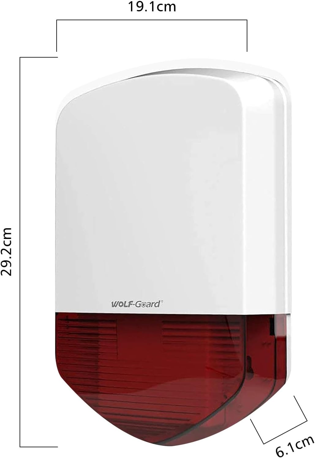
Figure 6: Detailed dimensions of the Wolf Guard LB-01A siren unit, showing its height (29.2cm), width (19.1cm), and depth (6.1cm).
Warranty and Support
The manufacturer, Chitongda (Brand: WOLF-GUARD), typically offers a limited warranty on their products. Please refer to the warranty information provided with your purchase documentation or contact the seller for details regarding warranty coverage and duration.
For technical support, troubleshooting assistance beyond this manual, or inquiries about additional accessories, please contact your point of purchase or the official WOLF-GUARD customer service channels. Contact information may be available on the product packaging or the brand's official website.
No official seller videos were found for this product that meet the criteria for inclusion in this manual.


