
1. Introduction
This manual provides essential information for the safe and efficient operation, setup, and maintenance of your KAKA INDUSTRIAL W-4812T 48-Inch Straight Sheet Metal Brake. Please read this manual thoroughly before operating the machine to ensure proper usage and to prevent injury or damage.
2. Safety Instructions
WARNING: Failure to follow these safety instructions may result in serious injury or death.
- Always wear appropriate personal protective equipment (PPE), including safety glasses, gloves, and sturdy footwear.
- Ensure the machine is securely anchored to a stable surface before operation.
- Keep hands and fingers clear of the bending and clamping areas during operation.
- Do not exceed the machine's stated capacity (12-gauge mild steel).
- Ensure all adjustments are tightened before operating the brake.
- Keep the work area clean and well-lit.
- Never operate the machine under the influence of drugs or alcohol.
- Only trained personnel should operate this equipment.
- Secure moving parts before performing maintenance or adjustments.
3. Product Overview and Components
The KAKA INDUSTRIAL W-4812T is a heavy-duty straight sheet metal brake designed for precise bending of various metal sheets. Key components include:
- Clamping Handle: Used to secure the sheet metal in place.
- Counterweight Arm: Assists in reducing effort during bending operations.
- Blade: The upper clamping bar that holds the material.
- Bending Leaf: The lower part that pivots to create the bend.
- Operating Handle: Used to actuate the bending leaf.
- L-shaped Support: Provides structural stability.
- Stop Rod: Used for setting precise bending angles.

Figure 1: Labeled diagram of the KAKA INDUSTRIAL W-4812T Straight Sheet Metal Brake, indicating the Counterweight Arm, Clamping Handle, Blade, Bending Leaf, Operating Handle, and L-shaped Support.
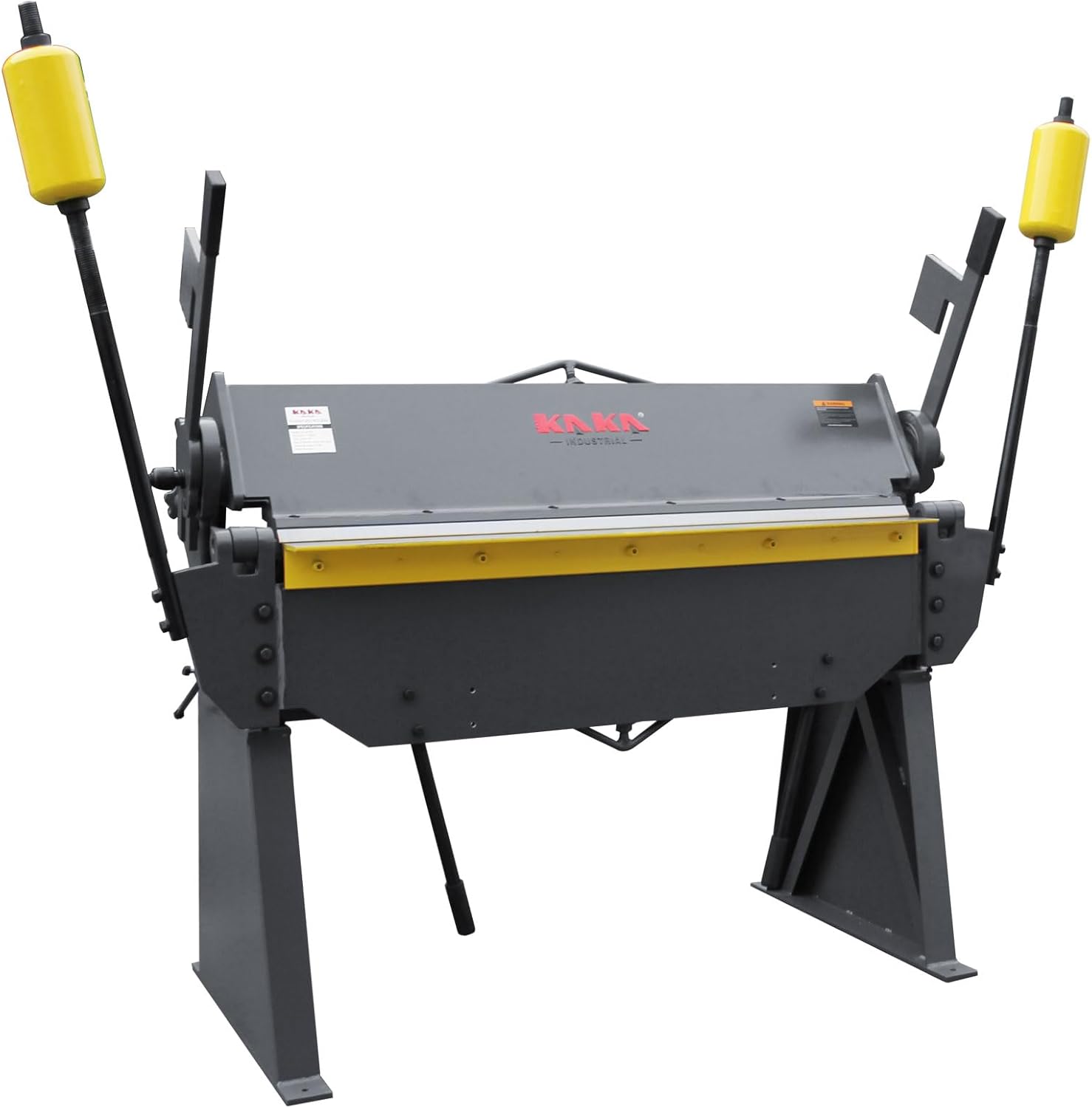
Figure 2: Front view of the KAKA INDUSTRIAL W-4812T 48-Inch Straight Sheet Metal Brake, showing its robust construction and handles.
4. Setup and Installation
- Unpacking and Inspection:
- Upon delivery, carefully inspect the packaging and the machine for any signs of damage. Report any damage to the carrier immediately.
- Ensure all components listed in the packing list are present.
- Note: This is a heavy item. A liftgate service is recommended for residential deliveries, and someone must be present to receive and sign for the shipment.
- Assembly:
- Assemble the L-shaped supports (legs) to the main body of the brake using the provided hardware. Ensure all bolts are securely tightened.
- Attach the counterweight arms and operating handles.
- Anchoring:
- Position the brake on a level, stable floor.
- Securely anchor the machine to the floor using appropriate fasteners to prevent movement during operation.
- Initial Adjustments:
- Verify that the clamping bar (blade) is parallel to the bending leaf. Adjust if necessary according to the manufacturer's guidelines for even clamping pressure.
- Familiarize yourself with the stop rod mechanism for setting bending angles.
5. Operating Instructions
Follow these steps for safe and effective bending operations:
- Prepare the Material:
- Ensure the sheet metal is clean and free of burrs or sharp edges.
- Mark the bend line clearly on the material.
- Set the Bending Angle:
- Adjust the stop rod to the desired bending angle (0-135 degrees). This limits the upward travel of the bending leaf.
- Position the Material:
- Lift the clamping handle to open the brake.
- Slide the sheet metal into the brake, aligning the marked bend line with the edge of the clamping blade.
- Ensure the material is centered and fully supported.
- Clamp the Material:
- Lower the clamping handle firmly to secure the sheet metal. Adjust the clamping force as needed to prevent slippage during bending.
- The heavy-duty handles and adjustable clamping force ensure stability.

Figure 3: Detail of the clamping mechanism, showing the handle and adjustable components for securing sheet metal.
- Perform the Bend:
- Using the operating handles, smoothly and steadily lift the bending leaf upwards until it reaches the set angle or the desired bend is achieved.
- The counterweights assist in reducing the physical effort required for bending.

Figure 4: Side view illustrating the bending leaf in an upward position during a bending operation.
- Release the Material:
- Lower the bending leaf back to its resting position.
- Lift the clamping handle to release the bent material.
- Carefully remove the finished piece.
6. Maintenance
Regular maintenance ensures the longevity and optimal performance of your sheet metal brake.
- Cleaning:
- After each use, clean the clamping blade and bending leaf to remove metal shavings and debris.
- Wipe down all surfaces to prevent rust, especially in humid environments.
- Lubrication:
- Periodically lubricate all pivot points, hinges, and threaded rods with appropriate machine grease or oil.
- Check for oil fittings on pins and lubricate accordingly.
- Inspection:
- Regularly inspect all bolts and fasteners for tightness. Tighten any loose hardware.
- Check the condition of the clamping blade and bending leaf for wear or damage. Replace components if necessary.
- Ensure the counterweights are securely attached.
- Storage:
- Store the machine in a dry environment to prevent corrosion.
7. Troubleshooting
| Problem | Possible Cause | Solution |
|---|---|---|
| Uneven bends or material slippage | Insufficient clamping force; material not properly aligned; worn clamping blade. | Increase clamping force; re-align material; inspect and replace clamping blade if worn. |
| Difficulty in operating bending leaf | Lack of lubrication on pivot points; material thickness exceeds capacity; counterweights loose. | Lubricate pivot points; ensure material is within 12-gauge mild steel capacity; check counterweight attachment. |
| Inaccurate bending angles | Stop rod improperly set; material spring-back. | Re-adjust stop rod for desired angle; account for material spring-back by over-bending slightly. |
| Machine instability during operation | Machine not securely anchored; loose leg bolts. | Ensure machine is firmly anchored to the floor; tighten all leg assembly bolts. |
8. Specifications
| Feature | Detail |
|---|---|
| Model Number | W-4812T (173107) |
| Bending Width | 48 inches |
| Capacity (Mild Steel) | 12-Gauge (0.1 inch) |
| Bending Angle | 0-135 Degrees (Adjustable) |
| Power Source | Hand-powered |
| Material | Metal |
| Color | Grey |
| Product Dimensions | 69 x 25 x 35 inches |
| Manufacturer | KAKA INDUSTRIAL LLC |
9. Warranty and Support
For warranty information, technical support, or to order replacement parts, please contact KAKA INDUSTRIAL LLC directly. Refer to your purchase documentation for specific warranty terms and contact details.
You can also visit the official KAKA INDUSTRIAL store on Amazon for additional product information and support resources: KAKA INDUSTRIAL Store