1. Product Overview
The Jung KNX Bus Coupler 2073 U is a system device designed for integrating KNX application modules into a KNX bus system. This component facilitates communication within the KNX network, ensuring seamless operation of connected devices. It is designed for flush-mounted installation and features a screw-fixing mechanism for secure placement.
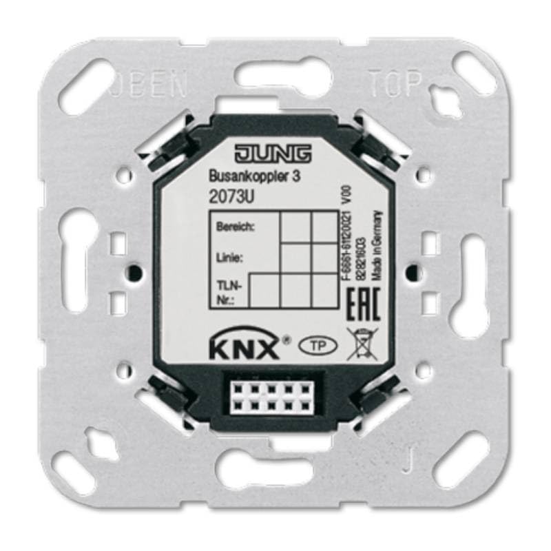
Figure 1: Front view of the Jung KNX Bus Coupler 2073 U, illustrating its compact design and connection points. The device is marked with "JUNG Busankoppler 3 2073U" and the KNX logo, indicating its compatibility with the KNX standard.
Key Features:
- KNX Bus System Compatibility: Fully compatible with the KNX bus system.
- Mounting Type: Designed for flush-mounted installation.
- Fixing Method: Secure 3-screw fixing for reliable installation.
- Sensor/Actuator Connections: Supports 1 sensor/actuator connection.
- Integration: Facilitates the integration of KNX application modules.
2. Safety Information
Please read this manual carefully before installation and operation. Failure to follow these instructions may result in damage to the device, property, or personal injury.
- Installation must be performed by a qualified electrician in accordance with national wiring regulations and local electrical codes.
- Ensure the power supply is disconnected before any installation, maintenance, or troubleshooting work.
- Do not operate the device if it is visibly damaged.
- Protect the device from moisture, dust, and extreme temperatures.
- This device is intended for commercial and private use within a KNX system.
3. Package Contents
Verify that all items are present and undamaged upon opening the package:
- 1 x Jung KNX Bus Coupler 2073 U
- (No additional accessories or manuals are typically included with this component, as it is part of a larger system installation.)
4. Setup and Installation
The Jung KNX Bus Coupler 2073 U is designed for flush-mounted installation. Proper installation is crucial for the device's functionality and safety within the KNX system.
Installation Steps:
- Preparation: Ensure the main power supply to the installation area is switched off at the circuit breaker.
- Mounting Location: Select a suitable flush-mounted box in the wall.
- Wiring: Connect the KNX bus line to the designated terminals on the bus coupler. Refer to the wiring diagram provided with your specific KNX application module for correct pin assignments.
- Securing the Device: Insert the bus coupler into the flush-mounted box. Use the three screw fixing points to securely fasten the device to the box. Ensure it is firmly seated and stable.
- Module Integration: Once the bus coupler is physically installed, the KNX application module (e.g., a switch, dimmer, or sensor module) can be clicked onto the bus coupler. Ensure a secure connection.
- Power Restoration: After verifying all connections are correct and secure, restore power to the circuit.
For detailed wiring diagrams and programming instructions, consult the documentation specific to the KNX application module being used with this bus coupler and the ETS (Engineering Tool Software) for KNX systems.
5. Operating Principles
The Jung KNX Bus Coupler 2073 U acts as an interface between the physical KNX bus line and the KNX application module. It does not have user-operable controls directly on the device itself. Its function is to provide the necessary electrical and data connection for the application module to communicate within the KNX network.
- Data Transmission: The bus coupler transmits data signals from the KNX bus to the connected application module and vice-versa.
- Power Supply: It draws power from the KNX bus line to operate the connected application module.
- Addressing: The addressing and configuration of the bus coupler and its associated application module are performed using the KNX ETS software. This involves assigning physical addresses and programming the desired functions.
Operation of the overall KNX system, including the functions enabled by this bus coupler, is managed through the programmed application modules (e.g., pressing a light switch, adjusting a thermostat). Refer to the specific application module's manual for operational details.
6. Maintenance
The Jung KNX Bus Coupler 2073 U is a low-maintenance device. Regular cleaning and inspection are generally sufficient.
- Cleaning: If necessary, gently wipe the visible parts of the device with a soft, dry, lint-free cloth. Do not use abrasive cleaners, solvents, or excessive moisture.
- Inspection: Periodically check for any signs of physical damage or loose connections. If any issues are observed, disconnect power and consult a qualified electrician.
- No User Serviceable Parts: The device contains no user-serviceable parts. Do not attempt to open or repair the unit.
7. Troubleshooting
Most issues related to the bus coupler are typically system-wide KNX communication problems or issues with the connected application module. This section provides general troubleshooting steps.
| Problem | Possible Cause | Solution |
|---|---|---|
| KNX device not responding. | No power to the KNX bus; incorrect wiring; faulty application module; incorrect ETS programming. | Check KNX bus power supply. Verify bus line connections to the coupler. Test the application module. Review ETS programming for correct addressing and functionality. |
| Intermittent communication. | Loose connections; bus line interference; faulty bus coupler. | Ensure all screw fixings and connections are tight. Check for sources of electrical interference. If issues persist, consider professional diagnosis of the bus coupler. |
| Device not recognized by ETS. | Incorrect physical address; bus line issue; ETS software problem. | Verify the physical address in ETS matches the device. Check bus line continuity. Restart ETS software and the KNX interface. |
For complex issues, it is recommended to contact a certified KNX installer or the manufacturer's technical support.
8. Specifications
| Attribute | Value |
|---|---|
| Manufacturer | Jung |
| Model Number | 2073 U |
| Part Number | 1 |
| Product Dimensions | 10 x 10 x 10 cm |
| Weight | 60 Grams |
| Color | Metal |
| Quantity in Package | 1 |
| Number of Parts | 1 |
| Usage | Commercial and private use |
| Package Contents | JUNG Busankoppler 2073U KNX 3 |
| Battery Required? | No |
| First Available Date | October 25, 2017 |
| Bus System | KNX (Yes), KNX-Radio (No), Radio Bus (No) |
| Mounting Type | Flush-mounted |
| Number of Sensor/Actuator Connections | 1 |
9. Warranty and Support
Jung products are manufactured to high quality standards. For specific warranty terms and conditions, please refer to the official Jung website or contact your local distributor. Keep your proof of purchase for warranty claims.
Technical Support:
For technical assistance, installation queries, or troubleshooting beyond the scope of this manual, please contact Jung customer support or a certified KNX professional.
- Manufacturer Website: www.jung.de (Please note: This is a general link and may not be specific to your region. Search for Jung's official website in your country.)
- KNX Association: For general information about the KNX standard and certified professionals, visit www.knx.org.


