
Introduction
This manual provides detailed instructions for the installation, operation, and maintenance of your Cerwin-Vega H71200.4 4-Channel Class A/B Amplifier. Designed for high performance and reliability, this amplifier is part of the HED (High Energy Design) series, balancing performance and value. Please read this manual thoroughly before installation and use to ensure proper function and to maximize the lifespan of your product.
The H71200.4 amplifier features:
- Latest High-Efficiency Class A/B Technology with Surface Mount Component Technology and 2-Layer PCB.
- Compact Size with an ambient backlit logo.
- RCA “Pass Thru” output for easy system expansion.
- Fully Variable Crossovers (12dB per octave).
- Handles HI and LO level input up to 12V.
- 2 Ohm Stable Stereo and 4 Ohm Mono (CH3/4) for 3-channel mode.
- Proprietary Vega Bass Boost EQ Up To 12dB.
- Power output: 120W x 4 @ 2Ω RMS, 80W x 4 @ 4Ω RMS, 240W x 2 @ 4Ω Bridged, 1200W MAX.
Safety Information
Always observe the following safety precautions during installation and operation:
- Disconnect the vehicle's negative battery terminal before starting any electrical work.
- Ensure all wiring is properly routed and secured to prevent damage or short circuits.
- Use appropriate gauge wiring for power, ground, and speaker connections as recommended by industry standards.
- Mount the amplifier securely in a location that allows for adequate ventilation and is protected from moisture and excessive heat.
- Avoid installing the amplifier in areas where it could interfere with the safe operation of the vehicle.
- If you are unsure about any aspect of installation, consult a professional car audio installer.
Package Contents
Upon opening the package, verify that all items are present:
- Cerwin-Vega H71200.4 Amplifier Unit
- User Manual (this document)
- Mounting Hardware (screws, washers)
- Allen Wrenches for terminal connections
- Remote Bass Knob (for mono amps, but often included with multi-channel for convenience)
- Wiring Harnesses (if applicable for high-level input)

Image: The Cerwin-Vega H71200.4 amplifier shown with its retail packaging, user manual, and included accessories such as wiring and mounting hardware.
Product Overview
The Cerwin-Vega H71200.4 amplifier is designed for robust audio performance in a compact form factor. Familiarize yourself with the various components and connections.
Top View
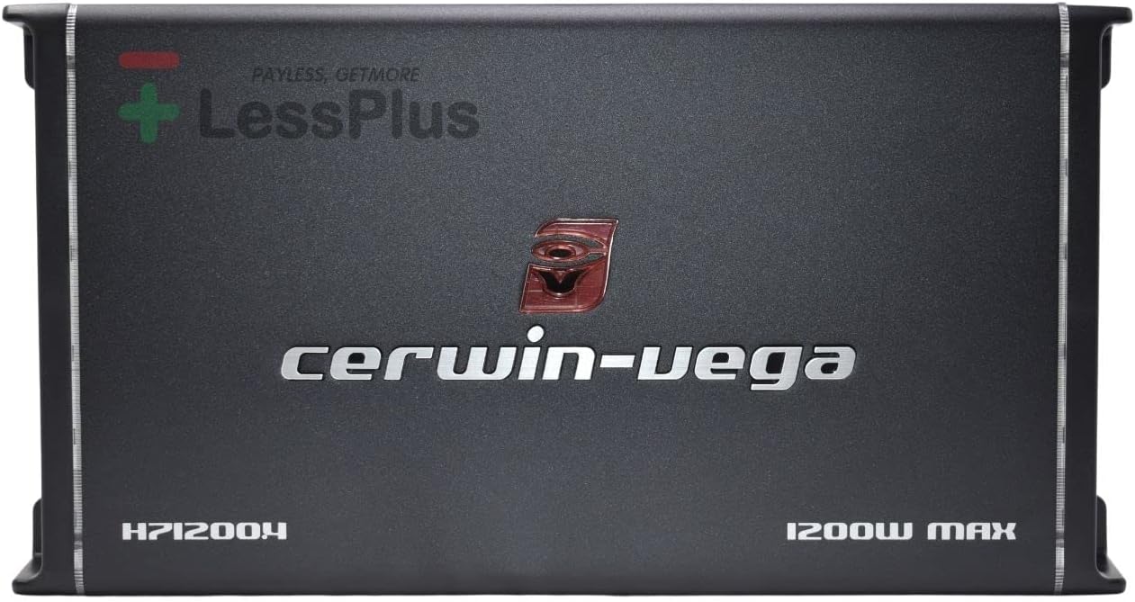
Image: Top view of the Cerwin-Vega H71200.4 amplifier, showcasing the brand logo and model number.
The top panel features the Cerwin-Vega logo and model designation, often backlit during operation.
Control Panel Side

Image: Close-up view of the control panel side of the Cerwin-Vega H71200.4 amplifier, showing RCA inputs, gain controls, and crossover switches.
This side houses the audio input and processing controls:
- LINE OUT (RCA): For passing the audio signal to another amplifier.
- LINE IN (RCA): Low-level audio inputs for Front and Rear channels.
- HI-INPUT: High-level speaker inputs for connecting directly to a factory head unit without RCA outputs.
- INPUT MODE: Switch to select 2-channel or 4-channel input operation.
- GAIN: Adjusts the input sensitivity to match the output of your head unit.
- X-OVER (Front/Rear): Switches for High Pass Filter (HPF), Low Pass Filter (LPF), or Full Range (FLAT).
- HIGH PASS / LOW PASS Frequency: Rotary controls to set the crossover frequency.
- VEGA BASS: Bass boost control (0dB to +12dB).
- POWER/PRO Indicators: LEDs to show power status and protection mode.
Power and Speaker Terminal Side

Image: Close-up view of the power and speaker terminal side of the Cerwin-Vega H71200.4 amplifier, showing power input, remote turn-on, ground, and speaker outputs.
This side contains the main power, ground, remote, and speaker connections:
- FUSE: Integrated fuses for protection.
- +12V: Main power input from the vehicle battery.
- REM: Remote turn-on input from the head unit.
- GND: Ground connection to the vehicle chassis.
- Speaker Outputs: Terminals for connecting your speakers (Front L/R, Rear L/R).
Setup and Installation
Proper installation is crucial for the performance and safety of your amplifier. Follow these steps carefully.
1. Mounting Location
- Choose a dry, well-ventilated location away from direct sunlight and heat sources.
- Ensure sufficient airflow around the amplifier's heatsink.
- Securely mount the amplifier using the provided hardware to prevent movement during vehicle operation.
2. Power Wiring
- Power (+12V): Run a heavy gauge power cable (e.g., 8 AWG or larger) directly from the vehicle's positive battery terminal to the amplifier's +12V terminal. Install an in-line fuse holder within 18 inches (45 cm) of the battery.
- Ground (GND): Connect a heavy gauge ground cable of the same length as the power cable from the amplifier's GND terminal to a clean, unpainted metal surface on the vehicle chassis. Ensure a solid electrical connection.
- Remote (REM): Connect a smaller gauge wire (e.g., 18 AWG) from the head unit's remote turn-on output to the amplifier's REM terminal. This wire turns the amplifier on and off with the head unit.
3. Audio Input Wiring
- Low-Level Input (RCA): Connect RCA cables from your head unit's pre-amp outputs to the amplifier's LINE IN (Front and Rear) RCA inputs.
- High-Level Input: If your head unit does not have RCA outputs, use the HI-INPUT terminals. Connect the speaker wires from your head unit directly to these inputs. Ensure correct polarity.
- Input Mode: Set the INPUT MODE switch to 2CH if using only two RCA inputs for all four channels, or 4CH if using separate Front and Rear RCA inputs.
4. Speaker Wiring
- Connect your speakers to the amplifier's speaker output terminals. Observe correct polarity (+ to + and - to -).
- The H71200.4 is 2Ω stable in stereo mode and 4Ω stable when bridged. Ensure your speaker impedance matches the amplifier's capabilities.
- For bridged operation (e.g., 2 channels into 1 subwoofer), connect the speaker to the designated positive and negative terminals for bridged mode (refer to the diagram on the amplifier or full manual).
Operating Instructions
Once installed, adjust the amplifier settings for optimal sound performance.
1. Gain Adjustment
- Start with the amplifier's GAIN controls set to minimum.
- Turn your head unit volume up to about 75% of its maximum.
- Slowly increase the GAIN control on the amplifier until you hear slight distortion, then back it off slightly. This matches the amplifier's input sensitivity to the head unit's output.
2. Crossover Settings
- HPF (High Pass Filter): Use for full-range speakers (e.g., door speakers) to block low frequencies that they cannot reproduce effectively. Set the frequency control to the speaker's recommended low-end cutoff.
- LPF (Low Pass Filter): Use for subwoofers to block high frequencies, allowing only bass to pass through. Set the frequency control to the desired upper bass limit (e.g., 80Hz-120Hz).
- FLAT (Full Range): Use if you want the amplifier to reproduce all frequencies, or if your head unit or external processor handles the crossovers.
3. Vega Bass Boost
- The VEGA BASS control allows you to boost low frequencies. Use sparingly to avoid distortion and speaker damage.
- Adjust to your preference, ensuring the sound remains clear and undistorted.
Maintenance
The Cerwin-Vega H71200.4 amplifier requires minimal maintenance to ensure long-term performance.
- Cleaning: Periodically wipe the amplifier's exterior with a soft, dry cloth to remove dust. Do not use liquid cleaners or solvents.
- Ventilation: Ensure that the amplifier's cooling fins are not obstructed by debris or other objects. Proper ventilation is essential to prevent overheating.
- Connections: Occasionally check all power, ground, remote, and speaker connections to ensure they are secure and free from corrosion. Loose connections can lead to poor performance or damage.
Troubleshooting
If you experience issues with your amplifier, refer to the following common problems and solutions before contacting support.
No Power / Amplifier Does Not Turn On
- Check Fuses: Verify the in-line fuse near the battery and the fuses on the amplifier itself. Replace if blown.
- Power Connection: Ensure the +12V power cable is securely connected to the battery and the amplifier.
- Ground Connection: Confirm the GND cable has a solid, clean connection to the vehicle chassis.
- Remote Turn-On: Check the REM wire connection to both the head unit and the amplifier. Ensure the head unit is providing a 12V signal to the remote wire when turned on.
No Sound Output
- Input Signal: Verify RCA or high-level input cables are securely connected and receiving a signal from the head unit.
- Speaker Connections: Check all speaker wires for secure connections and correct polarity. Ensure no bare wires are touching each other or the vehicle chassis.
- Gain Settings: Ensure GAIN controls are not set to minimum.
- Crossover Settings: Confirm crossover switches (HPF/LPF/FLAT) are set appropriately for your speakers.
- Protection Mode: If the "PRO" indicator is lit, the amplifier may be in protection mode due to overheating, low impedance, or a short circuit. Turn off the system, check connections, and allow the amplifier to cool.
Distorted Sound
- Gain Too High: Reduce the GAIN control on the amplifier.
- Head Unit Volume: Lower the volume on your head unit.
- Speaker Impedance: Ensure your speakers' impedance is compatible with the amplifier's output (2Ω stereo, 4Ω bridged).
- Crossover Settings: Adjust crossover frequencies to prevent speakers from playing frequencies outside their optimal range.
- Ground Loop: Check for proper grounding. A noisy ground connection can introduce distortion.
Specifications
Detailed technical specifications for the Cerwin-Vega H71200.4 amplifier:
| Feature | Specification |
|---|---|
| Model Number | H71200.4 |
| Channels | 4-Channel |
| Amplifier Class | Class A/B |
| Max Power | 1200W |
| RMS Power @ 2Ω | 140W x 4 |
| RMS Power @ 4Ω | 85W x 4 |
| RMS Power @ 4Ω Bridged | 280W x 2 |
| Crossover Frequency Range | 35Hz – 35KHz (LP/HP/FLAT) |
| Frequency Response | 15Hz – 35KHz |
| Dimensions (H x W x L) | 2.0” x 7.0” x 13.5” (50.8mm x 177.8mm x 342.9mm) |
| Voltage | 12 Volts |
| Item Weight | 7.32 pounds |
| Mounting Type | Surface Mount |
| UPC | 847169044564 |
Warranty Information
Cerwin-Vega Mobile CV products are designed and manufactured to the highest quality standards. For specific warranty terms and conditions, please refer to the warranty card included with your product or visit the official Cerwin-Vega Mobile CV website. Keep your purchase receipt as proof of purchase for any warranty claims.
Support
For technical assistance, troubleshooting beyond this manual, or general inquiries, please visit the official Cerwin-Vega Mobile CV website or contact their customer support directly. Contact information can typically be found on their website or in the product packaging.