1. Product Overview
The Cloudray MYJG-100W 220V CO2 Laser Power Supply is designed for 80-100W CO2 laser tubes, offering stable and efficient power delivery for laser engraving and cutting applications. It features quick response speed, high performance, and various safety measures to ensure reliable operation.
This power supply is compatible with a wide range of laser tubes from different manufacturers and includes an external ammeter with an LCD screen for real-time monitoring of current and status.

Figure 1: Cloudray 100W Laser Power Supply highlighting simple control, laser power adjustment, laser light test function, factory aging test, and high efficiency.
2. Specifications
Below are the detailed specifications for the Cloudray MYJG-100W 220V CO2 Laser Power Supply:
| Feature | Specification |
|---|---|
| Input Voltage | AC230V |
| AC Frequency | 47 ~ 440Hz |
| Max Output Voltage | 28KV |
| Max Output Current | 30mA |
| Size (L x W x H) | 230 x 161 x 91 mm (12.6 x 7.87 x 5.91 inches) |
| Weight | 2.8 kg (7.05 pounds) |
| Efficiency | 91% |
| MTBF (Mean Time Between Failures) | ≥ 30000 hours |
| Response Speed | ≤ 1ms |
| Voltage Range (High-Level) | ≥ 3V |
| Voltage Range (Low-Level) | ≤ 0.7V |
| Environment Temperature | -30° ~ +65°C |
| Cooling Method | Forced air cooling (fan cooling) |
| High Temperature Test | Full Load / 60°C / 12 hours |
| Start / Stop Test | 500 times 7 seconds |

Figure 2: Visual representation of the power supply's dimensions and key electrical specifications.
3. Setup and Installation
Proper installation is crucial for the safe and efficient operation of your laser system. Always ensure the power supply is disconnected from the main power source before beginning any installation or maintenance.
3.1 Wiring Connections
The power supply features clearly labeled terminals for input power, laser control signals, and high voltage output. Refer to the wiring diagram for correct connections.
- AC Input: Connect the main AC power supply (220V) to the designated AC terminals.
- High Voltage Output: Connect the high voltage output to your CO2 laser tube. Ensure secure connections and proper insulation.
- Control Signals: Connect TTL level signals for start/stop functionality. The power supply supports both active-high and active-low devices.
- Water Protection: Connect the water protection signal to ensure the laser tube is adequately cooled during operation.
- External Ammeter: Connect the external ammeter to monitor the processing current.

Figure 3: Detailed wiring diagram for the power supply, illustrating connections for AC input, high voltage output, and control signals.
3.2 Laser Tube Connection (Example)
When connecting the laser tube, ensure the water inlet and outlet are correctly attached to your cooling system. The high voltage cable from the power supply connects to the anode of the laser tube, and the cathode connects to the ground.
Video 1: Demonstration of connecting a CO2 laser tube to a power supply, including water cooling lines and electrical connections.
4. Operating Instructions
The Cloudray MYJG-100W power supply offers intuitive control and monitoring features.
4.1 Power On/Off
Ensure all connections are secure before powering on the unit. Use the main power switch to turn the power supply on or off.
4.2 Control Features
- TTL Level Control: The power supply uses TTL-level signals for precise control over laser operations, including start and stop functions.
- Test Button: A convenient button is included to manually check the laser output. This is useful for troubleshooting and alignment.
- Adjustable LCD Display: The external LCD display shows the current output amperage and the status of the water protection system and laser signal. A trimmer potentiometer allows for precise current adjustments.

Figure 4: The adjustable LCD display and control interface for monitoring and adjusting laser output.
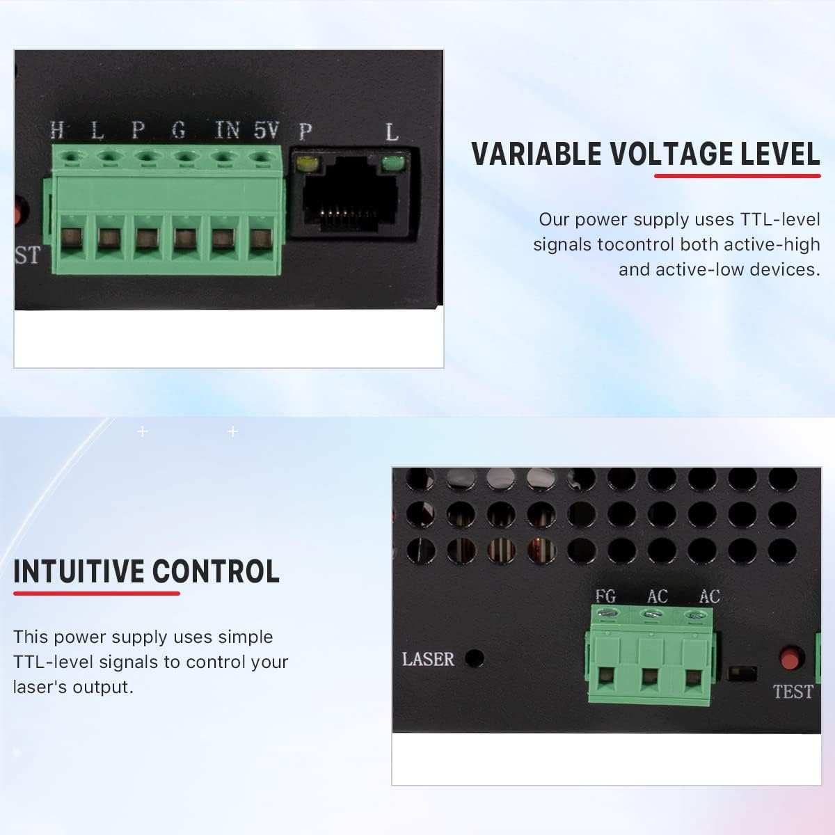
Figure 5: Detail of the TTL-level signal connections for controlling active-high and active-low devices.
5. Maintenance
Regular maintenance ensures the longevity and optimal performance of your power supply.
- Cleaning: Periodically clean the cooling fans and ventilation grilles to prevent dust accumulation, which can lead to overheating.
- Connection Checks: Regularly inspect all electrical connections for tightness and signs of wear or corrosion.
- Water Cooling System: Ensure your laser tube's water cooling system is functioning correctly and that water flows freely without blockages.

Figure 6: Rear view of the power supply, showing the cooling fan. Keep this area clear for proper airflow.
6. Troubleshooting
This section provides solutions for common issues you might encounter with your power supply.
6.1 Power Supply Fails to Start/No Output
- Possible Causes: Blown fuse (short circuit or overload), abnormal input voltage (incorrect 220V connection), control circuit failure (no signal from mainboard).
- Solutions:
- Check the fuse. Replace if blown and investigate short circuit causes.
- Measure input voltage. Ensure it matches power supply specifications (e.g., 220V ±10%).
- Test manual mode. Press the 'TEST' button. If the laser fires, the issue is in the control system (check signal wires or mainboard).

Figure 7: Troubleshooting steps for power supply startup issues.
6.2 Control Signal Unresponsive (Cannot Adjust via Mainboard)
- Possible Causes: Loose control cable connection (e.g., 6-pin green terminal), faulty water protection switch (WP) or control chip.
- Solutions:
- Reconnect control cables. Check for oxidation or loose contacts.
- Bypass WP test. Temporarily connect WP to GND. If laser fires, the issue is with the water protection switch.
- Replace water protection switch if faulty.

Figure 8: LCD display showing current output and water protection status, useful for diagnosing control issues.
6.3 Unstable Laser Output/Power Drop
- Possible Causes: Faulty current regulation circuit, laser tube aging or power mismatch, poor heat dissipation (fan failure or dust accumulation).
- Solutions:
- Inspect current control module. Verify adjustment functionality.
- Match laser tube power rating. Ensure power supply output matches tube specifications.
- Clean cooling fans. Ensure proper operation.

Figure 9: Troubleshooting steps for unstable laser output.
6.4 Frequent Fuse/Power Transistor Burnout
- Possible Causes: Shorted power transistors (MOSFET/IGBT failure), abnormal load (laser tube internal short), design flaw (insufficient heat dissipation).
- Solutions:
- Replace power transistors. Check driver circuit functionality.
- Test laser tube impedance. Rule out load short circuit.
- Enhance cooling. Add auxiliary fans or improve airflow.

Figure 10: Troubleshooting steps for fuse and power transistor issues.
7. Warranty and Support
For warranty information, please refer to the product packaging or contact Cloudray customer service directly. Cloudray offers technical support and assistance for their products.
For further assistance or to explore other Cloudray products, please visit the official Cloudray Store.


