1. Introduction
This manual provides detailed instructions for the installation, configuration, and operation of the NEXTION 50kg Load Cell Half-Bridge Strain Gauge and HX711 Amplifier Module. This system is designed for precise weight measurement applications, commonly found in digital scales. The load cells function as half-bridge strain gauges, and when combined with the HX711 amplifier, they provide an accurate and reliable solution for integrating weight sensing into various electronic projects, including those based on Arduino platforms.
2. Package Contents
Verify that all components listed below are present in your package:
- 4 x 50kg Half-Bridge Load Cells
- 1 x HX711 AD Amplifier Module

Description: This image displays the complete kit, including four individual 50kg half-bridge load cells, each with red, white, and black wires, and a single green HX711 amplifier module with pin headers for connection.
3. Setup and Wiring
The 50kg half-bridge load cells can be configured in several ways to achieve different measurement ranges and bridge types. The HX711 module is essential for converting the analog signal from the load cells into a digital format for microcontrollers like Arduino.
3.1 Load Cell Dimensions

Description: This image provides a technical drawing of a single 50kg load cell, detailing its length, width, and height, along with the spacing for mounting holes. Dimensions are provided in both metric (cm) and imperial (inches) units.
3.2 Wiring Configurations
The load cells are half-bridge strain gauges. To form a complete measurement system, they must be arranged into a full-bridge configuration, either with external resistors or with multiple load cells.
- Single Load Cell with External Resistors (50kg Range):
Use one 50kg load cell with appropriate external resistors to complete a full-bridge circuit. This configuration requires precise external resistance values for accurate measurements. - Two Load Cells (100kg Range):
Combine two 50kg load cells to form a full-bridge measurement. The total measuring range will be the sum of the two sensors, resulting in a 100kg capacity. - Four Load Cells (200kg Range):
Utilize all four 50kg load cells to construct a full-bridge measurement. This setup provides the highest capacity, summing to 200kg. This is the most common configuration for digital scales.
3.2.1 Four Load Cell Wiring Example (Arduino Integration)

Description: This image shows a detailed wiring schematic. Four load cells are arranged in a square pattern, representing a typical scale setup. Each load cell's wires (red, white, black) are connected to the HX711 module's E+, E-, A+, A-, B+, B- pins. The HX711 module then connects to an Arduino board via VCC, GND, DT (Data), and SCK (Clock) pins.

Description: This image presents a schematic of four load cells integrated into a scale base. It highlights the internal wiring of the load cells (W: white, R: red, B: black) and their connections to the HX711 module, forming a complete bridge circuit for weight measurement. Power input and signal output connections are clearly labeled.
3.2.2 Load Cell Mounting Example

Description: This image illustrates a three-step process for setting up the load cells. The first panel shows four load cells positioned on a base. The second panel shows the HX711 module placed in the center, with wires from the load cells connected to it. The third panel shows the HX711 module connected to an Arduino board, completing the circuit.
4. Operating Principles
The load cells operate on the principle of strain gauges, which change electrical resistance when subjected to mechanical stress (weight). These half-bridge sensors require a full Wheatstone bridge configuration to produce a differential voltage signal proportional to the applied load.
4.1 Wheatstone Bridge Configuration
A Wheatstone bridge is an electrical circuit used to measure an unknown electrical resistance by balancing two legs of a bridge circuit, one leg of which includes the unknown component. In this application, the load cells form the variable resistors in the bridge.

Description: This image displays a classic Wheatstone bridge circuit diagram. It shows four resistors labeled SG1 through SG4, representing the strain gauges within the load cells. The diagram indicates the 'Excitation +' and 'Excitation -' points for power input, and 'Output +' and 'Output -' for signal measurement.
4.2 HX711 Amplifier Module
The HX711 is a 24-bit analog-to-digital converter (ADC) specifically designed for weigh scales and industrial control applications to interface directly with a bridge sensor. It provides a digital output signal that can be easily read by a microcontroller.
Description: This image presents the internal block diagram of the HX711 chip. It details components such as the analog supply regulator, programmable gain amplifier (PGA), 24-bit analog-to-digital converter, and digital interface, along with its various input/output pins for connection to the load cells and a microcontroller.
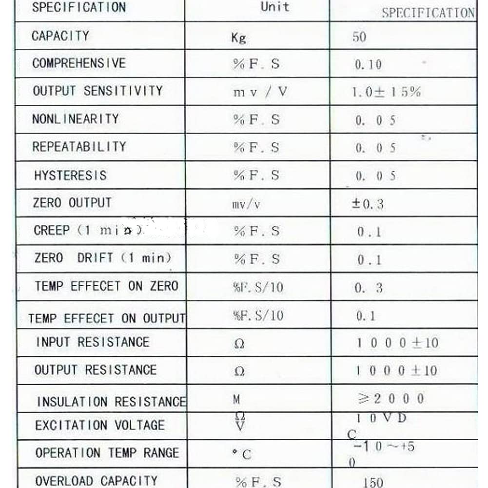
5. Specifications
Key technical specifications for the 50kg Load Cell and HX711 Module:
| Feature | Specification |
|---|---|
| Load Cell Type | Half-Bridge Strain Gauge |
| Single Load Cell Capacity | 50 kg |
| HX711 ADC Resolution | 24-bit |
| Recommended Uses | Weighing scales, industrial control, DIY projects |
| Product Dimensions (Load Cell) | Approximately 1.5 x 1 x 0.7 inches |
| Item Model Number | 8541791593 |
| Manufacturer | NEXTION |
6. Troubleshooting
If you encounter issues during setup or operation, consider the following common troubleshooting steps:
- No Reading or Erratic Readings:
- Verify all wiring connections are secure and correct according to the diagrams.
- Ensure the HX711 module is receiving proper power (VCC and GND).
- Check for any short circuits or loose connections.
- Confirm that the microcontroller code for the HX711 is correctly implemented and calibrated.
- Inaccurate Readings:
- Perform a calibration procedure for your scale setup. This typically involves measuring known weights and adjusting the calibration factor in your code.
- Ensure the load cells are mounted correctly and are not experiencing any binding or uneven pressure.
- Check for environmental factors such as temperature fluctuations, which can affect strain gauge readings.
- Module Not Detected by Microcontroller:
- Confirm the DT and SCK pins are connected to the correct digital pins on your microcontroller.
- Verify the power supply voltage to the HX711 module is within its operating range (2.7V to 5.5V).
7. Warranty and Support
For specific warranty information and technical support, please refer to the seller's policies or contact the manufacturer directly. General support for DIY projects involving these components can often be found in online communities and forums dedicated to electronics and microcontrollers.