1. Introduction
This Walfront DC 12V-48V Automatic Emergency Power Switch Controller is designed to provide uninterrupted power by seamlessly switching between a main power source and a backup battery. When the main power source is active, the controller uses it as the primary supply. If the main power fails, it automatically switches to the connected battery. Once the main power is restored, the controller reverts to the main power source.
This module is equipped with convenient screw terminals for easy cable connection and automatically detects the voltage within the 12V to 48V DC range. It is widely used in applications requiring continuous power, such as incubators, laptops, and network systems.
2. Features
- Automatic emergency battery switching functionality.
- Seamless transition between main power and battery backup.
- Equipped with screw terminals for secure and convenient cable connections.
- Automatic voltage detection for DC 12V to 48V systems.
- Ideal for applications requiring uninterrupted power supply.
3. Specifications
| Specification | Value |
|---|---|
| Voltage Range | DC 12V ~ 48V |
| Load Current | 10 Amperes (Max) |
| Operating Mode | ON-OFF-ON |
| Contact Type | Normally Closed |
| Connector Type | Screw Terminal |
| Material | PCB |
| Dimensions (L x W x H) | 5 x 3 x 1.8 cm (1.9 x 1.2 x 0.7 inches) |
| Weight | Approx. 22g |
4. Setup and Installation
Before installation, ensure all power sources are disconnected to prevent electrical shock or damage to the module.
- Identify Terminals: The module has clearly labeled screw terminals for DC input (main power), BAT input (battery), and OUT (load). Refer to the diagrams below.
- Connect Main Power: Connect your primary DC power source (e.g., power adapter or switched-mode power supply) to the 'DC+' and 'DC-' terminals.
- Connect Battery: Connect your backup battery to the 'BAT+' and 'BAT-' terminals. Ensure the battery voltage matches the main power source voltage and is within the 12V-48V DC range.
- Connect Load: Connect your device or load (e.g., incubator, laptop, network equipment) to the 'OUT+' and 'OUT-' terminals.
- Verify Connections: Double-check all connections for correct polarity and secure fastening of wires in the screw terminals.
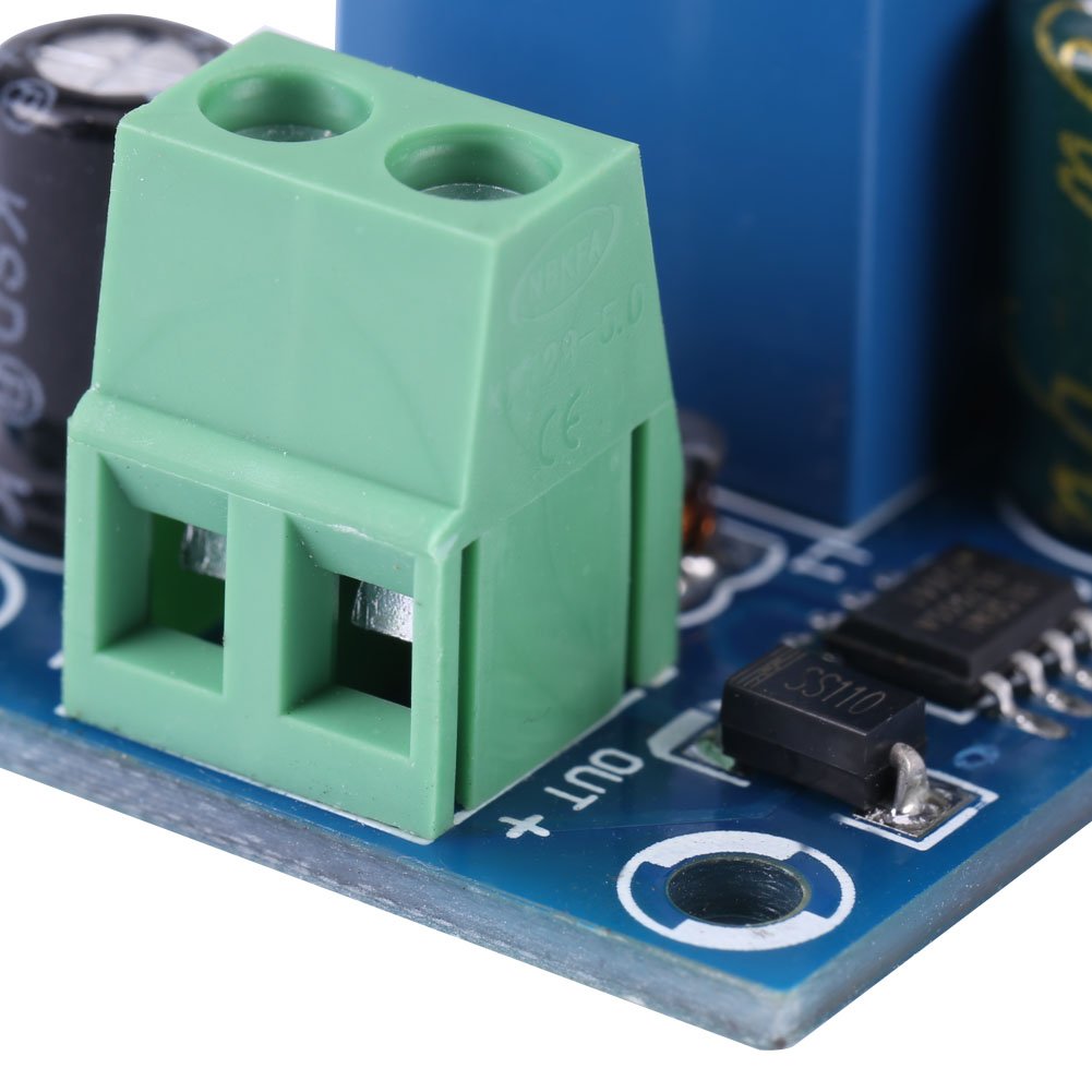
Figure 1: Labeled diagram of the Walfront Automatic Emergency Power Switch Controller, showing the battery terminal, power adapter terminal, 10A relay, power adapter indicator light, and load terminal. Note the 0.16cm thick double-layer PCB.
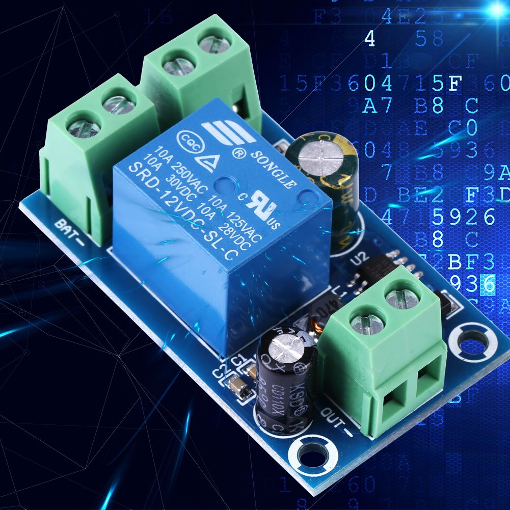
Figure 2: Connection diagram illustrating how to connect the DC power source, battery, and load to the module. The module automatically switches to battery power when the main power is off, and is suitable for DC 12V, 24V, 36V, and 48V systems.

Figure 3: Physical dimensions of the controller module: 5cm (1.96 inches) length, 3cm (1.18 inches) width, and 1.8cm (0.7 inches) height.
5. Operation
Once properly connected, the controller operates automatically:
- Main Power Active: When the main DC power source is connected and supplying power, the controller will use this as the primary power supply for the connected load. The power adapter indicator light will be on.
- Main Power Failure: If the main DC power source is disconnected or fails, the controller will automatically and instantly switch the power supply to the connected battery. The power adapter indicator light will turn off.
- Main Power Restoration: When the main DC power source is re-established, the controller will automatically switch back to using the main power supply.
6. Maintenance
The Walfront Automatic Emergency Power Switch Controller is designed for low maintenance. Follow these guidelines to ensure optimal performance and longevity:
- Keep Clean: Ensure the module is kept clean and free from dust, dirt, and moisture. Use a soft, dry cloth for cleaning.
- Secure Connections: Periodically check that all screw terminal connections are tight and secure to prevent intermittent power issues or arcing.
- Ventilation: Ensure the module is installed in an area with adequate ventilation to prevent overheating, although this module has low power dissipation.
- Environmental Conditions: Avoid exposing the module to extreme temperatures, high humidity, or corrosive environments.
7. Troubleshooting
If you encounter issues with your Walfront Automatic Emergency Power Switch Controller, consider the following:
- No Power Output / Incorrect Switching:
- Voltage Mismatch: Ensure that the voltages of the main power source, the backup battery, and the connected load are all the same. This module is designed for systems where all components operate at the same nominal voltage (e.g., all 12V, all 24V, etc.).
- Loose Connections: Check all screw terminal connections (DC input, BAT input, OUT) to ensure they are securely fastened and that wires have good contact.
- Power Source Issues: Verify that both your main DC power source and your battery are providing the correct voltage and sufficient current.
- Momentary Power Interruption During Switching:
- This is normal behavior. During the automatic switching process, there will be a momentary power failure lasting less than 1 second. This is inherent to the design and not an indication of a fault.
- Overload Protection:
- Ensure the total current drawn by your load does not exceed the module's maximum load current of 10 Amperes. Overloading can cause the module to malfunction or be damaged.
