1. Introduction
This user manual provides comprehensive instructions for the installation, operation, maintenance, and troubleshooting of the IP-COM G3224P 24-Port Managed PoE Switch. Please read this manual thoroughly before using the device to ensure proper and safe operation.
The IP-COM G3224P is a high-performance managed Power over Ethernet (PoE) switch designed for small to medium-sized businesses and enterprise networks. It offers 24 Gigabit Ethernet ports with PoE+ capabilities and additional SFP ports for fiber uplinks, providing flexible and scalable network solutions.
2. Product Overview
2.1 Package Contents
- IP-COM G3224P 24-Port Managed PoE Switch
- Power Cord
- Rackmount Kit (brackets and screws)
- Rubber Feet (for desktop placement)
- Quick Installation Guide
2.2 Front Panel Description
The front panel of the IP-COM G3224P switch features various ports and LED indicators for status monitoring.
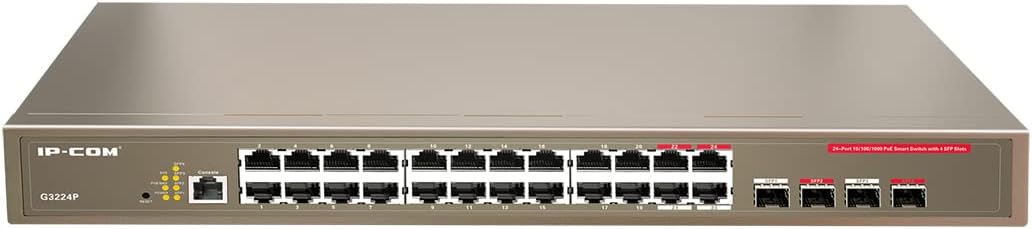
Figure 2.1: IP-COM G3224P Front Panel Layout
This image displays the front panel of the IP-COM G3224P switch. On the left, the IP-COM logo and model number G3224P are visible. To the right, there are LED indicators for SYS, PoE MAX, and individual port status. A console port is also present. The main section features 24 Gigabit Ethernet RJ45 ports, arranged in two rows, with port numbers 1 through 24. On the far right, there are four SFP ports labeled SFP1, SFP2, SFP3, and SFP4, which are used for fiber optic uplinks.
2.3 LED Indicators
| LED Indicator | Status | Description |
|---|---|---|
| SYS | Green (Solid) | System is operating normally. |
| SYS | Green (Blinking) | System is booting up or firmware is being upgraded. |
| PoE MAX | Red (Solid) | PoE power budget is nearing or exceeding its limit. |
| Link/Act (Per Port) | Green (Solid) | Port is linked. |
| Link/Act (Per Port) | Green (Blinking) | Port is transmitting or receiving data. |
| PoE (Per Port) | Yellow (Solid) | PoE power is being supplied to the connected device. |
3. Setup and Installation
3.1 Safety Precautions
- Ensure the power supply voltage matches the switch's requirements (240V as per specifications).
- Do not block ventilation openings.
- Keep the device away from water, fire, and high temperatures.
- Do not attempt to open or repair the device yourself.
3.2 Rackmount Installation
- Attach the provided rackmount brackets to the sides of the switch using the included screws.
- Secure the switch into a standard 19-inch equipment rack using appropriate rack screws (not included).
- Ensure adequate airflow around the switch for proper cooling.
3.3 Desktop Installation
- Attach the provided rubber feet to the bottom of the switch.
- Place the switch on a flat, stable surface with sufficient ventilation.
3.4 Connecting the Switch
- Power Connection: Connect the power cord to the power inlet on the rear panel of the switch and then to a grounded power outlet.
- Network Devices: Connect network devices (e.g., computers, servers, IP cameras, VoIP phones) to the RJ45 ports (1-24) on the front panel using standard Ethernet cables.
- PoE Devices: For PoE-powered devices, simply connect them to any of the RJ45 ports. The switch will automatically detect and provide power if the device is PoE compliant.
- Uplink Connections: Use the SFP ports (SFP1-SFP4) for fiber optic uplinks to other network devices or the core network. Insert compatible SFP transceivers into the SFP slots before connecting fiber optic cables.
- Console Connection (Optional): For initial configuration or advanced management, connect a console cable from your computer to the console port on the switch.
4. Operating Instructions
4.1 Initial Power On
After connecting the power cord, the switch will automatically power on. Observe the SYS LED indicator. It will blink during boot-up and turn solid green once the system is ready.
4.2 Basic Network Connectivity
Once powered on, the switch will automatically detect connected devices. The Link/Act LED for each connected port will illuminate solid green, indicating a successful link. It will blink when data is being transmitted or received.
4.3 PoE Operation
When a PoE-compatible device is connected to a port, the switch will negotiate power delivery. The PoE LED for that port will turn yellow, indicating that power is being supplied. Monitor the PoE MAX LED; if it turns red, the total PoE power budget is being approached or exceeded, and you may need to reduce the number of PoE devices or use a higher-capacity power source.
4.4 Management Access
The IP-COM G3224P is a managed switch, offering various configuration options via a web-based GUI, CLI (Command Line Interface) via the console port, or SNMP. Refer to the detailed management guide (usually available on the manufacturer's website) for advanced configuration, including VLANs, QoS, port mirroring, and security settings.
- Web GUI: Access the switch's web interface by typing its default IP address (check the Quick Installation Guide or manufacturer's documentation) into a web browser.
- CLI: Connect via the console port using a terminal emulator (e.g., PuTTY) with appropriate serial port settings.
5. Maintenance
5.1 Cleaning
- Regularly clean the exterior of the switch with a soft, dry cloth.
- Do not use liquid or aerosol cleaners.
- Ensure ventilation openings are free from dust and obstructions.
5.2 Firmware Updates
Periodically check the IP-COM official website for firmware updates. Keeping the firmware up-to-date ensures optimal performance, security, and access to new features. Follow the instructions provided with the firmware update package carefully.
5.3 Environmental Considerations
Ensure the switch operates within its specified environmental conditions (temperature, humidity) to prevent damage and ensure longevity.
6. Troubleshooting
| Problem | Possible Cause | Solution |
|---|---|---|
| No power / SYS LED off | Power cord not connected or power outlet faulty. | Check power cord connection. Try a different power outlet. |
| No link on a port (Link/Act LED off) | Cable issue, device off, or incorrect port. | Check Ethernet cable. Ensure connected device is powered on. Try a different port or cable. |
| PoE device not powering on (PoE LED off) | Device not PoE compliant, cable issue, or power budget exceeded. | Verify device is PoE compliant. Check cable. Check PoE MAX LED; if red, reduce PoE load. |
| Network performance issues | Cable quality, network congestion, or incorrect configuration. | Use high-quality Ethernet cables. Check for network loops. Review switch configuration (VLANs, QoS). |
| Cannot access web management interface | Incorrect IP address, network settings, or firewall. | Verify the switch's IP address. Ensure your computer is on the same subnet. Disable temporary firewalls. |
If problems persist, consult the full product documentation or contact IP-COM technical support.
7. Specifications
| Feature | Detail |
|---|---|
| Model | G3224P |
| Ports | 24 x 10/100/1000Base-T (RJ45) with PoE+, 4 x 1000Base-X (SFP) |
| Switching Capacity | 56 Gbps |
| Forwarding Rate | 41.66 Mpps |
| PoE Standard | IEEE 802.3af/at |
| Input Voltage | 240 Volt |
| Dimensions (L x W x H) | 29 x 44 x 44 cm |
| Weight | 15 Kilograms |
| Rackmount | Yes |
| Management | Managed (Web GUI, CLI, SNMP) |
Note: Specifications are subject to change without prior notice.
8. Warranty and Technical Support
8.1 Warranty Information
IP-COM products typically come with a limited warranty. Please refer to the warranty card included with your product or visit the official IP-COM website for detailed warranty terms and conditions specific to your region and purchase date.
8.2 Technical Support
For technical assistance, product inquiries, or troubleshooting beyond the scope of this manual, please contact IP-COM technical support. Support contact information can usually be found on the official IP-COM website or in the product's packaging.
IP-COM Official Website: www.ip-com.com.cn


