
1. Introduction
This manual provides essential information for the safe and effective installation, operation, and maintenance of the OBO Bettermann V25-B+C/3+NPE FS Surge Protection Device. Please read these instructions carefully before installation and keep them for future reference.
The V25-B+C/3+NPE FS is designed to protect electrical installations from transient overvoltages (surges) caused by lightning strikes or switching operations. It is a complete unit, pre-mounted and ready for connection, suitable for various TN and TT systems.
2. Product Overview
The OBO Bettermann V25-B+C/3+NPE FS is a combined lightning current and surge arrester, featuring an encapsulated non-extinguishing zinc oxide varistor. It is designed for use in standard distributor housings.
- Complete Unit: Consists of a cover and base, pre-mounted and ready for connection.
- Multi-connection Terminals: Equipped with a new Multibase base for versatile wiring.
- System Compatibility: Suitable for both TN and TT earthing systems.
- Remote Signalling: Includes a potential-free normally open (NO) contact for function monitoring.
- Visual Function Display: Features a plug-in arrestor with a dynamic cut-off unit and a visual indicator for operational status.

Figure 1: Front view of the OBO Bettermann V25-B+C/3+NPE FS Surge Protection Device, showing the four modules (three orange, one blue) and connection terminals.
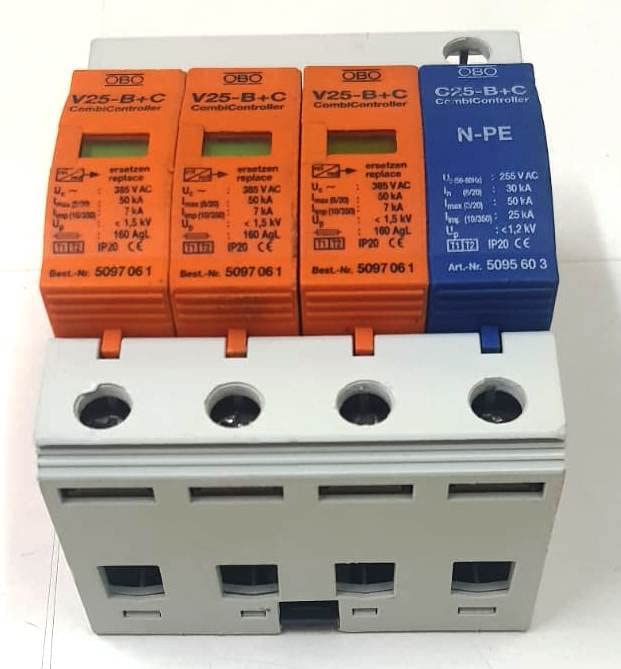
Figure 2: Angled view of the surge protection device, highlighting the modular design and branding.
3. Safety Information
WARNING: Installation and maintenance must only be performed by qualified electricians in accordance with national wiring regulations and safety standards. Failure to comply may result in serious injury or damage to equipment.
- Always disconnect power before installing or servicing the device.
- Ensure proper grounding connections are made.
- Do not operate the device if it appears damaged.
- Observe all local and national electrical codes.
4. Setup and Installation
The V25-B+C/3+NPE FS is designed for easy installation within standard electrical distribution housings. It features a plug-in design for the arrestor modules.
4.1 Mounting
- Ensure the main power supply to the installation is switched off and locked out.
- Mount the device onto a DIN rail within the distribution housing. The device is designed for secure rail mounting.
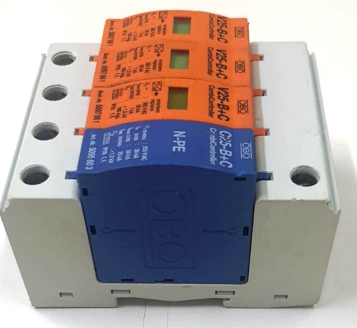
Figure 3: Top-down view illustrating the connection terminals for wiring.
4.2 Wiring Connections
Connect the device according to the wiring diagram provided with the product and national electrical codes. The Multibase base provides multi-connection terminals for flexible wiring.
- Connect the phase conductors (L1, L2, L3) to the respective orange modules.
- Connect the Neutral (N) and Protective Earth (PE) conductors to the blue N-PE module.
- Ensure all connections are tight and secure.
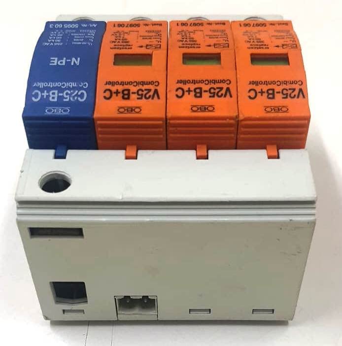
Figure 4: Bottom view of the device, showing the base structure and mounting mechanism for a DIN rail.
4.3 Remote Signalling Contact
The device includes a potential-free normally open (NO) contact for remote function monitoring. Connect this contact to a suitable monitoring system if remote status indication is required.
5. Operating Instructions
Once correctly installed and wired, the OBO Bettermann V25-B+C/3+NPE FS operates automatically to protect against surges. It does not require manual intervention during normal operation.
5.1 Visual Function Display
Each plug-in arrestor module is equipped with a visual function display. This indicator provides immediate feedback on the operational status of the module.
- Green Indicator: The module is operational and providing surge protection.
- Red Indicator: The module has responded to a surge event and is no longer operational. It requires replacement.

Figure 5: Close-up view of the individual modules, highlighting the visual status indicators (green for operational, red for failed).
6. Maintenance
The OBO Bettermann V25-B+C/3+NPE FS is largely maintenance-free. However, periodic checks are recommended to ensure continued protection.
- Visual Inspection: Regularly check the visual function display on each module. If any indicator is red, the corresponding module needs replacement.
- Connection Integrity: Periodically inspect wiring connections for tightness and signs of corrosion.
- Module Replacement: To replace a failed module (indicated by a red display), switch off the power supply, carefully pull out the faulty plug-in module, and insert a new, identical module. Ensure the new module clicks securely into place.
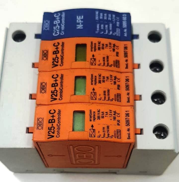
Figure 6: Angled view demonstrating the plug-in nature of the individual surge protection modules.
7. Troubleshooting
This section addresses common issues and their resolutions.
7.1 Visual Indicator is Red
- Problem: One or more modules show a red indicator.
- Cause: The module has absorbed a significant surge and is no longer functional.
- Solution: Replace the affected plug-in module(s) as described in the Maintenance section (Section 6).
7.2 Remote Signalling Not Working
- Problem: The remote monitoring system does not receive signals from the device.
- Cause: Incorrect wiring of the remote signalling contact, or a fault in the monitoring system.
- Solution: Check the wiring of the potential-free NO contact. Verify the functionality of the remote monitoring system independently.
8. Specifications
| Feature | Detail |
|---|---|
| Brand | OBO Bettermann |
| Model Number | V25-B+C/3+NPE FS |
| Type | Combined Lightning Current and Surge Arrester (Type 1+2) |
| System Compatibility | TN and TT systems |
| Arrestor Type | Encapsulated non-extinguishing zinc oxide varistor |
| Special Feature | Easy to install, Visual function display, Remote signalling |
| Product Dimensions (LxWxH) | 6 x 7 x 10 Centimeters |
| Material | Zinc |
| Remote Signalling | Potential-free NO contact |
9. Warranty and Support
For warranty information and technical support, please refer to the official OBO Bettermann website or contact your local distributor. Keep your purchase receipt for warranty claims.