1. Introduction
This manual provides comprehensive instructions for the installation, operation, and maintenance of the RATTMMOTOR DDCS V2.1 4 Axis CNC Controller System. This standalone motion controller is designed for use with CNC routers, engraving machines, and milling machines, offering offline control capabilities and supporting G-code programming. Please read this manual thoroughly before operating the device to ensure safe and efficient use.
2. Safety Information
- Always ensure the power supply is disconnected before performing any wiring or maintenance.
- Operate the controller in a clean, dry environment, free from excessive dust, moisture, and corrosive gases.
- Ensure proper grounding of all connected equipment to prevent electrical shock.
- Do not attempt to open or modify the controller unit. Refer all servicing to qualified personnel.
- Wear appropriate personal protective equipment (PPE) when operating CNC machinery.
- Familiarize yourself with the emergency stop procedures for both the controller and the connected machine.
3. Product Overview
The RATTMMOTOR DDCS V2.1 is a high-performance 4-axis CNC controller system featuring a 500KHz pulse output, USB connectivity, and an offline operation mode. It replaces traditional Mach3 systems, providing a dedicated and stable control solution for various CNC applications.
3.1 Key Features
- 4-axis control for X, Y, Z, and A axes.
- Maximum output pulse frequency of 500KHz per axis.
- Offline operation via USB flash drive for G-code input.
- Integrated display and keypad for direct control and monitoring.
- Supports standard G-code programming.
- Compatible with stepper and servo motor drive systems.
3.2 Components and Interface

Figure 1: Front view of the DDCS V2.1 CNC Controller, showing the display screen and control buttons.
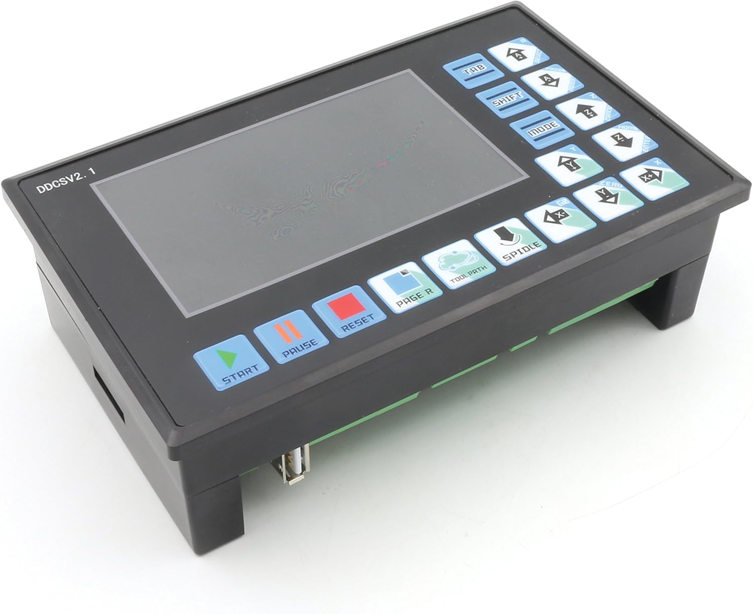
Figure 2: Angled front view, highlighting the ergonomic button layout for easy operation.

Figure 3: Side view of the controller, showing its compact form factor.

Figure 4: Rear view displaying the input, spindle, stepper, and MPG ports with clear labeling for wiring.

Figure 5: Another detailed rear view, providing a closer look at the various connection terminals and power input.
The controller features a clear LCD display for real-time status and parameter viewing, along with a membrane keypad for input and navigation. The rear panel includes all necessary ports for power, motor drivers, limit switches, emergency stop, and other peripheral connections.
4. Setup
4.1 Wiring Diagram
Refer to the detailed wiring diagram provided in the separate wiring guide for your specific machine configuration. Ensure all connections are secure and correctly matched to the corresponding terminals on the DDCS V2.1 controller. Pay close attention to power supply polarity, motor driver connections (STEP/DIR), limit switches, and emergency stop circuits.
4.2 Initial Power-Up
- After completing all wiring, double-check every connection for accuracy and security.
- Connect the 24V DC power supply to the controller.
- Power on the controller. The display should illuminate, and the system will initiate its boot sequence.
- Follow any on-screen prompts for initial setup, such as language selection or axis configuration.
- Verify that all connected motors respond correctly to manual jog commands before proceeding with automated operations.
5. Operating Instructions
5.1 User Interface Navigation
The controller's interface consists of a display screen and a keypad. Use the arrow keys to navigate menus and parameters. The 'ENTER' or 'OK' button confirms selections, and 'ESC' or 'BACK' returns to the previous screen.
5.2 Loading G-Code
- Save your G-code file onto a USB flash drive. Ensure the file format is compatible (e.g., .nc, .tap, .gcode).
- Insert the USB flash drive into the USB port on the controller.
- Navigate to the 'File Management' or 'Program' menu on the controller.
- Select the desired G-code file from the USB drive. The controller will load and display the program information.
5.3 Starting a Job
- After loading the G-code, ensure the workpiece is properly secured and the tool is correctly installed and offset.
- Set the workpiece origin (G54, G55, etc.) as required by your G-code program.
- Press the 'START' button to begin the machining process.
- Monitor the machine's operation closely. Use the 'PAUSE' button for temporary stops and 'RESET' for emergency stops or to clear errors.
5.4 Manual Control (Jogging)
Use the dedicated axis control buttons (X+, X-, Y+, Y-, Z+, Z-, A+, A-) to manually move the machine axes. Adjust the jog step size or continuous jog speed as needed through the controller's settings.
6. Maintenance
- Cleaning: Regularly clean the controller's exterior with a soft, dry cloth. Avoid using harsh chemicals or abrasive materials. Ensure no dust or debris accumulates in the ventilation slots.
- Firmware Updates: Check the RATTMMOTOR official website periodically for firmware updates. Follow the provided instructions carefully for any update procedures.
- Connection Checks: Periodically inspect all wiring connections for looseness or damage. Tighten any loose terminals.
7. Troubleshooting
| Problem | Possible Cause | Solution |
|---|---|---|
| Controller does not power on. | No power supply; incorrect voltage; faulty power cable. | Check power connections; verify 24V DC supply; replace cable if damaged. |
| Motors do not move. | Incorrect wiring to motor drivers; motor drivers not enabled; emergency stop engaged; limit switch triggered. | Verify motor driver wiring (STEP/DIR); check driver power and enable signals; disengage E-stop; check limit switch status. |
| G-code file not recognized. | Incorrect file format; corrupted USB drive; unsupported G-code commands. | Ensure file is .nc, .tap, or .gcode; try a different USB drive; simplify G-code or check for controller-specific syntax. |
| Inaccurate machining. | Incorrect steps per unit setting; mechanical backlash; loose couplings. | Calibrate steps per unit in controller settings; inspect mechanical components for wear or looseness. |
8. Specifications
| Feature | Specification |
|---|---|
| Brand | RATTMMOTOR |
| Model | DDCS V2.1 |
| Control Axes | 4 (X, Y, Z, A) |
| Max. Output Pulse Frequency | 500 KHz per axis |
| Input Voltage | 24 Volts DC |
| Connectivity | USB (for G-code loading) |
| Manufacturer | Changzhou Rattm Motor Co.,Ltd |
| UPC | 785004502674 |
9. Warranty and Support
RATTMMOTOR products are manufactured to high-quality standards. For warranty information, technical support, or service inquiries, please refer to the documentation included with your purchase or visit the official RATTMMOTOR website. Please have your product model number (DDCS V2.1) and purchase details ready when contacting support.


