1. Product Overview
This manual provides detailed instructions for the uxcell DC 12V Gear Motor with Encoder, Model a17092900ux0537. This compact and robust motor is designed for various applications including robotics, RC models, and DIY projects, offering precise speed control and positional feedback through its integrated encoder.

Figure 1: Main view of the uxcell DC 12V Gear Motor with Encoder.
2. Key Features
- Rated Voltage: 12V DC, with an operating voltage range of 6-24V.
- Speed: 463 RPM (no-load).
- Integrated Encoder: Provides positional feedback with 6 color-coded leads, terminated by a 6-female header with a 0.1" pitch.
- Compact Design: Gearbox size 25x17mm (0.98x0.67inch), Motor size 24.5x31mm (0.96x1.22inch).
- D-Shape Shaft: 4x10mm (0.16x0.39inch) for secure coupling.
- Mounting: Face plate features two M3 threaded mounting holes, 18mm apart.
- Applications: Suitable for robotics, RC models, and other projects requiring precise directional control.
3. Technical Specifications
| Parameter | Value |
|---|---|
| Brand | uxcell |
| Model Name | gear |
| Rated Voltage | 12V DC |
| Voltage Range | 6-24V |
| No-load Speed | 463 RPM |
| Load Speed | 370 RPM |
| No-load Current | 46mA |
| Load Current | 300mA |
| Stall Current | 1A |
| Torque | 0.23kg.cm |
| Reduction Ratio | 9.28:1 |
| Gearbox Size (D*L) | 25x17mm (0.98x0.67inch) |
| Motor Size (D*L) | 24.5x31mm (0.96x1.22inch) |
| Shaft Size (D*L) | 4x10mm (0.16x0.39inch) |
| Encoder Cable Length | 20cm (7.87inch) |
| Mounting Hole Size | M3 |
| Material | Metal |
| Item Weight | Approx. 100g (3.2 ounces) |

Figure 2: Detailed dimensions of the gear motor and shaft.
4. Setup and Installation
4.1 Mounting the Motor
The motor features two M3 threaded mounting holes on its face plate, spaced 18mm apart. Use appropriate M3 screws to secure the motor to your application's chassis or mounting bracket. Ensure the mounting is firm to prevent vibration and misalignment during operation.

Figure 3: M3 mounting holes on the motor's face plate.
4.2 Wiring Instructions
The motor includes a 6-pin connector for both motor power and encoder signals. It is crucial to correctly identify each wire's function to ensure proper operation and prevent damage. Note: There have been reports of variations in wire color assignments. Always verify connections before applying power.

Figure 4: General wiring diagram for the gear motor and encoder. Verify with actual PCB markings if available.
Based on common configurations and user feedback, the wiring is typically as follows:
- Motor Power:
- Red: Motor Positive (+)
- White: Motor Negative (-)
- Encoder Signals:
- Black: Encoder Ground (GND)
- Blue: Encoder Vcc (Positive supply, typically 3.3V to 5V, but Hall effect ICs can often handle up to 24V-30V with appropriate pull-up resistors)
- Green: Hall Sensor A Output (Encoder Channel A)
- Yellow: Hall Sensor B Output (Encoder Channel B)
The A and B outputs of the Hall sensor are square waves, approximately 90° out of phase, providing quadrature encoding for direction and speed detection.
Important Note on Wiring Discrepancies:
Some users have reported variations in wire color mapping. If the motor does not function as expected, or if the encoder signals are incorrect, it is recommended to consult the markings on the encoder's PCB (Printed Circuit Board) if visible, or to test the connections carefully with a multimeter before applying full power. The PCB may have labels such as M1, M2 for motor, GND, VCC, C1, C2 for encoder.
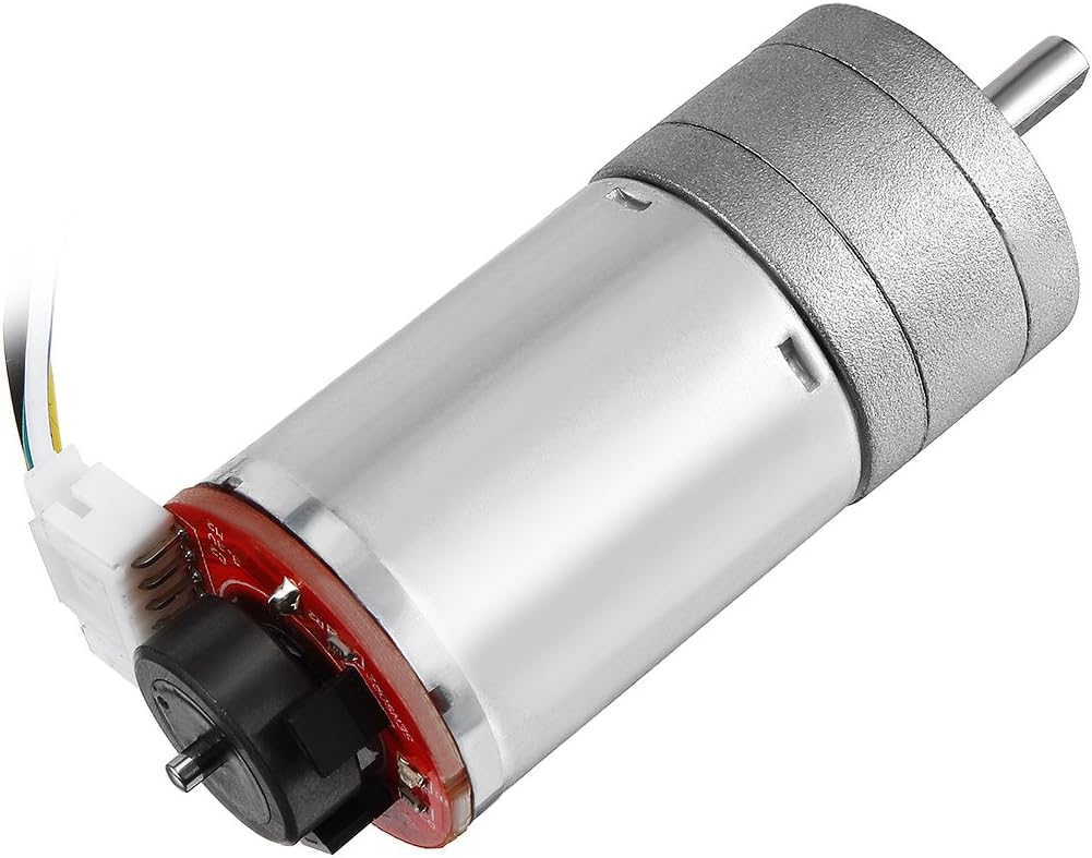
Figure 5: Side view showing the encoder board and connected wires.
5. Operation
Once properly installed and wired, the motor can be controlled by applying a DC voltage within its specified range (6-24V) to the motor power leads (Red and White). The direction of rotation can be reversed by swapping the polarity of the motor power leads.
The integrated encoder provides feedback on the motor's rotation. By monitoring the square wave outputs from Hall Sensor A and B, you can determine the motor's speed and direction. This is typically done using a microcontroller or dedicated motor controller.
- Speed Control: Adjust the input voltage (within the 6-24V range) or use Pulse Width Modulation (PWM) to control the motor's speed.
- Direction Control: Reverse the polarity of the voltage applied to the motor leads.
- Encoder Usage: Connect the encoder outputs (Green, Yellow) to interrupt pins or a dedicated encoder interface on your microcontroller to count pulses and determine rotational position and velocity.
6. Maintenance
The uxcell gear motor is designed for durability and requires minimal maintenance. However, adhering to the following guidelines can prolong its lifespan and ensure optimal performance:
- Keep Clean: Regularly clean the motor's exterior to prevent dust and debris accumulation, especially around the shaft and ventilation points.
- Avoid Overload: Do not exceed the specified torque or current ratings to prevent overheating and premature wear of the motor and gearbox.
- Check Connections: Periodically inspect all electrical connections for tightness and corrosion. Loose connections can lead to intermittent operation or damage.
- Environmental Conditions: Operate the motor within its intended temperature and humidity ranges. Avoid exposure to excessive moisture or corrosive environments.
- Lubrication: The gearbox is pre-lubricated. Avoid disassembling the gearbox unless absolutely necessary, as this can compromise its sealing and lubrication.
7. Troubleshooting
| Problem | Possible Cause | Solution |
|---|---|---|
| Motor does not run | No power, incorrect wiring, motor stalled, faulty motor. |
|
| Incorrect motor direction | Motor power polarity reversed. | Swap the Red and White motor power leads. |
| Encoder not providing feedback or incorrect readings | Incorrect encoder wiring, faulty encoder, software issue. |
|
| Motor runs slowly or with reduced torque | Under-voltage, excessive load, worn gears. |
|
8. Warranty and Support
For warranty information or technical support regarding your uxcell DC 12V Gear Motor with Encoder, please contact uxcell customer service through their official website or the retailer from whom the product was purchased. Please have your model number (a17092900ux0537) and purchase details available when contacting support.
You can visit the uxcell store for more information: uxcell Official Store