1. Introduction
This user manual provides detailed instructions for the installation, operation, and maintenance of the AKO D14012 12V Panel-Mounted Digital Temperature Display. This device is designed for precise temperature indication in either Celsius (°C) or Fahrenheit (°F), featuring selectable NTC/PTC probe programs and a simple single-button interface for settings. Please read this manual thoroughly before using the device to ensure correct operation and to prevent damage.
2. Safety Information
- Electrical Safety: Ensure the power supply is disconnected before installation or maintenance. The device operates on 12V DC. Incorrect voltage or polarity can damage the unit.
- Installation: Installation should only be performed by qualified personnel. Follow all local electrical codes and regulations.
- Environment: Do not expose the device to excessive moisture, dust, or extreme temperatures outside its specified operating range.
- Probe Handling: Handle the temperature probe carefully. Do not bend or crimp the cable excessively.
- Cleaning: Use a soft, dry cloth for cleaning. Do not use abrasive cleaners or solvents.
3. Package Contents
Verify that all items are present and undamaged upon opening the package:
- AKO D14012 Digital Temperature Display Unit
- Temperature Probe (NTC/PTC compatible)
- Mounting Clips (2 units)
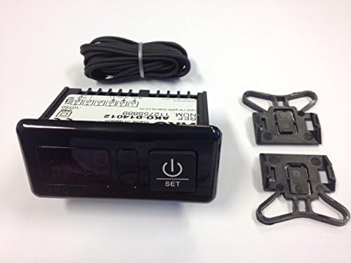
Figure 3.1: Contents of the AKO D14012 package, showing the main display unit, the coiled temperature probe, and two mounting clips.
4. Product Overview
The AKO D14012 is a compact digital temperature display designed for integration into control panels. It features a clear digital display for temperature readings and a single "SET" button for configuration. The unit is powered by 12V DC and connects to an external temperature probe.
4.1. Key Components
- Digital Display: Shows the current temperature.
- SET Button: Used to access and adjust device settings and parameters.
- Probe Input: Connection point for the NTC/PTC temperature sensor.
- Power Input: Terminals for 12V DC power supply.
5. Setup
5.1. Panel Mounting
The AKO D14012 is designed for panel mounting. Create an opening in your control panel with the following dimensions:
- Width: 70.5 mm
- Height: 28.5 mm
Insert the display unit into the opening and secure it using the provided mounting clips on the sides of the unit.

Figure 5.1: Panel cutout dimensions and rear wiring diagram for the AKO D14012 unit.
5.2. Wiring Connections
Refer to Figure 5.1 for the wiring diagram. Ensure power is disconnected before making any connections.
- Probe Connection: Connect the temperature probe to the designated terminals on the left side of the unit (labeled "Sonda" in the diagram).
- Power Supply: Connect the 12V DC power supply to the terminals on the right side. Ensure correct polarity: connect 12V to the positive terminal and 0V to the negative terminal (labeled "12V=" and "0V" respectively in the diagram). The device is designed for 12V DC operation.
After all connections are made, you can apply power to the unit.
6. Operating Instructions
6.1. Power On
Once correctly wired and powered, the display will illuminate and show the current temperature measured by the probe.
6.2. Viewing Temperature
The primary function of the device is to continuously display the temperature. The reading will update automatically as the temperature changes.
6.3. Accessing Settings (SET Button)
The "SET" button is used to access and modify various parameters of the device, such as temperature units (°C/°F) and probe type (NTC/PTC). Specific programming steps will depend on the firmware version. Generally:
- Short Press: May display a specific parameter or confirm a selection.
- Long Press: Typically enters programming mode or saves changes.
Consult the full programming guide for detailed instructions on setting specific parameters, including temperature alarms or calibration, if applicable to your model.
7. Maintenance
7.1. Cleaning
To clean the display unit, gently wipe the surface with a soft, dry, or slightly damp cloth. Do not use harsh chemicals, abrasive cleaners, or solvents, as these can damage the display or casing.
7.2. Probe Inspection
Periodically inspect the temperature probe and its cable for any signs of damage, wear, or corrosion. Replace the probe if any damage is observed to ensure accurate readings.
8. Troubleshooting
| Problem | Possible Cause | Solution |
|---|---|---|
| No display / Unit not powering on | No power supply; Incorrect wiring (polarity); Faulty unit. | Check 12V DC power connection and polarity. Ensure power source is active. Verify wiring. If problem persists, contact support. |
| Incorrect temperature reading | Faulty probe; Incorrect probe type selected; Probe not properly connected; Environmental interference. | Check probe connection. Ensure correct NTC/PTC probe type is configured in settings. Inspect probe for damage. Relocate probe if exposed to external heat sources. |
| Display shows "Err" or similar error code | Probe disconnected or faulty; Out of temperature range. | Check probe connection and integrity. Ensure measured temperature is within -50°C to +150°C range. |
9. Specifications
| Model Number | D14012 |
| Brand | AKO |
| Manufacturer | AKO Electronica |
| Power Source | 12V DC |
| Display Type | Digital |
| Temperature Range | -50 °C to +150 °C |
| Sensor Input | NTC Thermistor (PTC selectable) |
| Mounting Type | Panel-mounted |
| Panel Cutout Dimensions | 70.5 mm (Width) x 28.5 mm (Height) |
| Special Features | Programmable, °C/°F selectable |
10. Warranty and Support
For warranty information, technical support, or service inquiries, please contact your local AKO distributor or the point of purchase. Keep your purchase receipt as proof of purchase for warranty claims.


