1. Introduction
This manual provides comprehensive instructions for the Digital Low Voltage Protector Disconnect Switch. This module is designed to protect 12-36V lead-acid and lithium batteries from over-discharge, thereby extending their operational life. It functions as a smart switch, disconnecting the load when the battery voltage drops below a preset threshold and reconnecting when it recovers.

Figure 1: Digital Low Voltage Protector Disconnect Switch
2. Key Features
- Over-Discharge Protection: Automatically disconnects the battery when it reaches a preset low voltage, preventing damage and extending battery life.
- Memory Function: Retains user settings even after power loss, ensuring consistent operation.
- Delay Turn-On: Configurable delay (0-999 seconds) for reconnection after a disconnect, preventing rapid cycling.
- Voltage Controller: Operates as a relay switch to turn output on/off; it does not change the voltage.
- Wide Input Voltage Range: Supports DC 12-36V.
- High Accuracy: Voltage detection accuracy of 0.1V.
- Low Power Consumption: Consumes less than 1.5W.
- High Current Capacity: Supports up to 20A maximum amperage before breaker trips.

Figure 2: Module Features Overview
3. Technical Specifications
| Parameter | Value |
|---|---|
| Model | HCW-M635 |
| Input Voltage | DC 12-36V |
| Accuracy | 0.1V |
| Power Consumption | <1.5W |
| Maximum Amperage | 20A |
| Board Size (L x W x H) | 57 x 42 x 19mm (2.24 x 1.65 x 0.75 inches) |
| Item Weight | 0.634 ounces |
| Contact Type | Normally Closed |
| Terminal | Screw |
| Country of Origin | China |

Figure 3: Detailed Product Parameters
4. Setup and Wiring
Proper wiring is essential for the safe and effective operation of the module. Refer to the wiring diagram below for connection details.
- Input Power (VIN): Connect your DC 12-36V power source (e.g., battery) to the 'VIN' terminals. Ensure correct polarity: '+' to positive, '-' to negative.
- Output Load (VOUT): Connect your load (e.g., lighting system, motor) to the 'VOUT' terminals. The module acts as a switch for this load.
- Indicator LED: The onboard LED indicates the status of the relay (output).

Figure 4: Wiring Diagram
Demonstration Video
Video 1: Official demonstration of the low voltage cutoff module, showcasing its functionality to prolong battery life by preventing over-discharge.
5. Operating Instructions
The module features two buttons for setting parameters: '+' and '-'.
Setting Disconnect Voltage (P1)
- Double press the "+" button. The decimal point on the display will start flashing.
- Use the "+" or "-" button to set your desired disconnect voltage. This is the voltage at which the module will cut off power to the load.
- Wait a few seconds for the display to stop flashing, and the setting will be saved automatically.
Setting Difference Value (P2)
- Double press the "-" button. The decimal point on the display will start flashing.
- Use the "+" or "-" button to set the difference value. This value is added to the disconnect voltage to determine the reconnect voltage. For example, if disconnect is 12V and difference is 2V, it will reconnect at 14V.
- Wait a few seconds for the display to stop flashing, and the setting will be saved automatically.
Calibrating Input Voltage (P3)
- Long press the "+" button. The LED screen will flash.
- Use the "+" or "-" button to calibrate the input voltage display to match an external voltmeter if necessary.
- Wait a few seconds for the display to stop flashing, and the setting will be saved automatically.
Setting Delay Turn-On (P4)
- Long press the "-" button.
- Then press the "+" or "-" button to set the delay value 'T'. This is the interval (in seconds) between a disconnect and the module turning on again. The time range is 0-999 seconds. Note that no decimal point is displayed for this setting.
- Wait a few seconds for the display to stop flashing, and the setting will be saved automatically.
Viewing Settings
- Press the "+" button once to view the set disconnect voltage.
- Press the "-" button once to view the set difference value.

Figure 5: Programming Instructions
Important Note on Low Voltage Cutoff Logic
This module operates based on the following logic:
- If the battery voltage is lower than the set disconnect voltage (e.g., 12V) for the first connection or during use, there will be no output voltage.
- If the battery voltage is higher than the disconnect voltage but lower than the reconnect voltage (disconnect voltage + difference value) for the first connection, there will be no output voltage.
- If the battery voltage is higher than the reconnect voltage (e.g., 14V) for the first connection, there will be output voltage.
- During use, if there is output voltage and the battery voltage drops below the disconnect voltage (e.g., 12V), the load will be disconnected. It then needs to be charged to the reconnect voltage (e.g., 14V) before it will provide output voltage again.

Figure 6: Low Voltage Cutoff Logic
6. Applications
This module is suitable for a variety of applications requiring battery over-discharge protection:
- Automobile Battery Systems
- Electric Vehicle Batteries
- General Storage Batteries
- Solar Panel Systems
- Lighting Systems
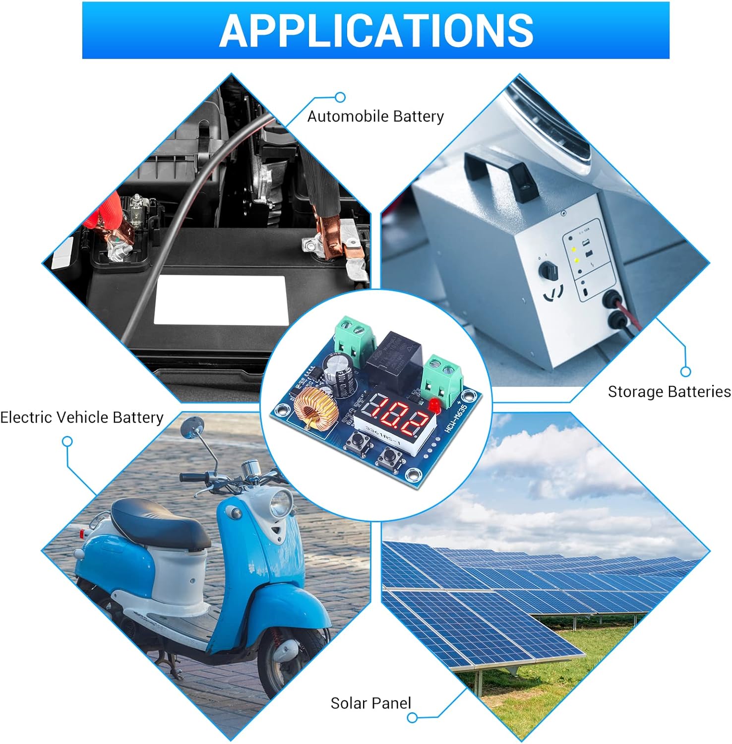
Figure 7: Common Applications
7. Maintenance
- Keep the module in a dry environment to prevent moisture damage.
- Avoid exposing the module to extreme temperatures or direct sunlight.
- Ensure all connections are secure and free from corrosion.
- Periodically check the display for accurate voltage readings.
- Clean the module gently with a dry, soft cloth if necessary. Do not use liquid cleaners.
8. Troubleshooting
- No Display/No Power: Check input voltage polarity and ensure connections are secure. Verify the power source is within the 12-36V DC range.
- No Output to Load: Confirm the battery voltage is above the reconnect voltage (disconnect voltage + difference value). Check the load's functionality independently.
- Frequent On/Off Cycling: This may occur if the difference value is set too low. Increase the difference value (P2) to provide a wider voltage hysteresis.
- Inaccurate Voltage Reading: Calibrate the input voltage using the P3 setting as described in the Operating Instructions.
- Module Not Disconnecting: Verify the disconnect voltage (P1) is set correctly and that the battery voltage is actually dropping below this threshold.
9. Warranty and Support
For any technical assistance, warranty claims, or further inquiries, please contact the manufacturer or seller directly. Keep your purchase receipt for warranty purposes.
An additional user manual in PDF format can be found here.