1. Introduction
This manual provides detailed instructions for the DROK REES-1822 DC Buck Converter. This module is an adjustable step-down voltage regulator designed to convert a higher DC input voltage to a lower, stable DC output voltage. It features an LCD display for real-time monitoring of input/output voltage, current, and power, along with constant voltage (CV) and constant current (CC) capabilities.

Figure 1: DROK DC Buck Converter (REES-1822) with LCD Display and protective case.
2. Safety Information
- Ensure correct input and output polarity. Reverse connection can damage the module.
- The input voltage must be at least 0.8V higher than the desired output voltage for proper buck conversion.
- Do not exceed the maximum input voltage of 32V or the maximum output current of 12A (with enhanced heat dissipation).
- For continuous operation at higher power (above 120W or 8A), ensure adequate heat dissipation by improving airflow or adding additional cooling.
- Avoid short circuits on the output terminals during operation, although the module has short circuit protection.
- Handle the module with care to prevent electrostatic discharge (ESD) damage.
3. Product Features
- Input Voltage Range: DC 5.3V-32V
- Output Voltage Range: DC 1.2V-32V (Adjustable)
- Output Current: Up to 8A (12A Max with enhanced heat dissipation)
- Output Power: Up to 120W (160W Max with enhanced heat dissipation)
- Display: Integrated LCD screen showing input/output voltage, current, and power.
- Precision: Voltage precision 0.05V, Current precision 0.005A.
- Protection: Reverse-connect protection, short circuit protection, over current protection.
- Case: Protective acrylic case to shield the circuit board from dust.
- Heat Sink: Included for improved thermal management.

Figure 2: Key features highlighted for the DROK DC Buck Converter.
4. Package Contents
Upon opening your package, verify that all components are present:
- 1x DROK DC Buck Converter Module
- 1x Acrylic Top Plate
- 1x Acrylic Bottom Plate
- 4x Brass Standoffs
- 8x Screws
- 2x Blue Button Caps
- 1x Aluminum Heat Sink (pre-installed or separate)
Video 1: Official DROK video demonstrating the assembly and basic operation of the buck converter module.
5. Assembly Instructions
The protective acrylic case requires simple assembly:
- Carefully peel off the protective films from both sides of the acrylic top and bottom plates.
- Align the brass standoffs with the mounting holes on the bottom acrylic plate.
- Place the buck converter module onto the standoffs, ensuring the holes align.
- Secure the module to the standoffs using the provided screws.
- Place the top acrylic plate over the module, aligning the holes with the standoffs.
- Secure the top plate with the remaining screws.
- Attach the blue button caps to the ON/OFF and IN/OUT buttons.
6. Controls and Display
The module features an LCD display and several controls for easy operation:
6.1. Buttons
- ON/OFF Button: Short press to toggle the output voltage ON or OFF. Long press to set the default power-on state (output ON or OFF).
- IN/OUT Button: Short press to switch the LCD display between input voltage/current and output voltage/current. Long press to switch the display to show output current or output power.
6.2. Potentiometers
- CV (Constant Voltage) Potentiometer: Rotate clockwise to increase the output voltage.
- CC (Constant Current) Potentiometer: Rotate clockwise to increase the setting current for over current protection.
6.3. Indicators
- Output Voltage Indicator: Lights up when output voltage is present.
- Constant Current Indicator (Red): Lights up when the load current reaches the set current limit.

Figure 3: Overview of the LCD display modes and button functions.
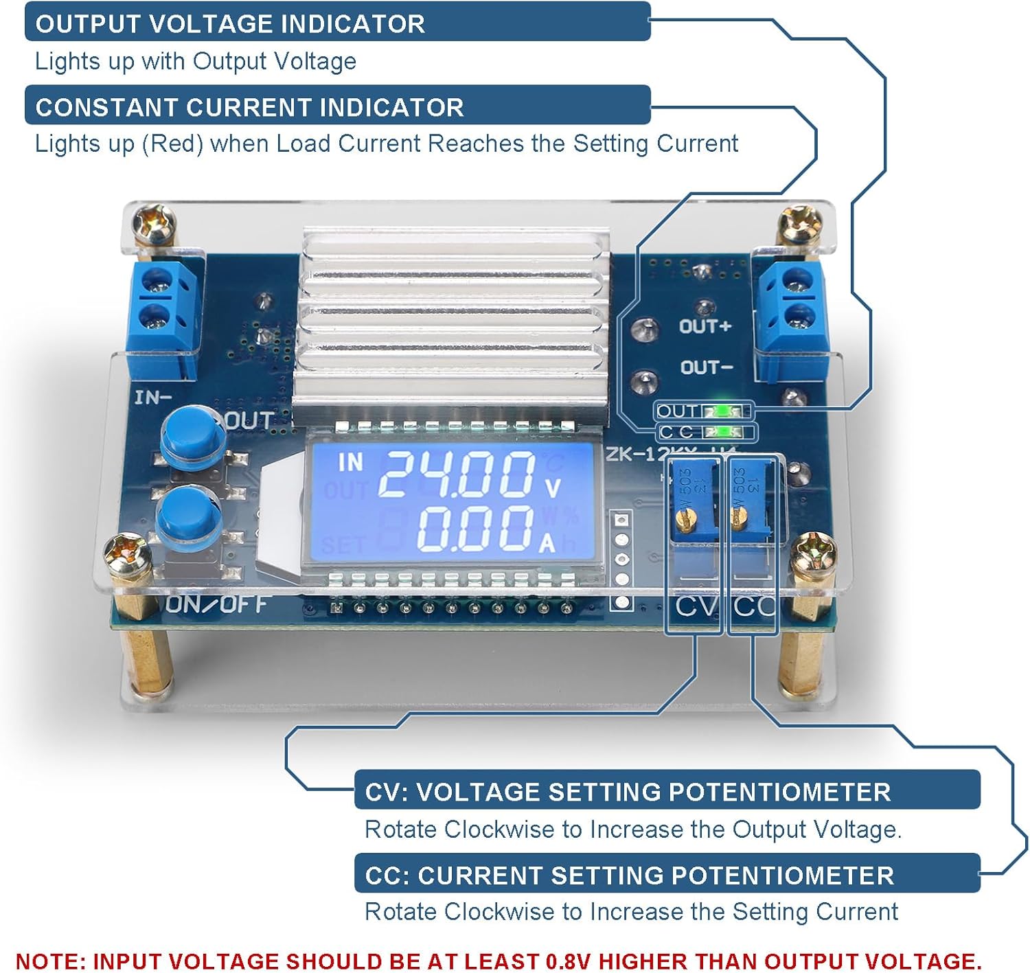
Figure 4: Location and function of the CV and CC potentiometers and indicator lights.
7. Operating Instructions
7.1. Connecting Power
- Connect your DC input power source to the IN+ and IN- terminals. Ensure correct polarity.
- Connect your load to the OUT+ and OUT- terminals. Ensure correct polarity.
- Verify that the input voltage is within the specified range (DC 5.3V-32V).
7.2. Adjusting Output Voltage (CV)
Before connecting a sensitive load, it is recommended to adjust the output voltage first:
- Power on the module.
- Use the IN/OUT button to display the output voltage on the LCD.
- Rotate the CV potentiometer (usually the one closer to the output terminals) clockwise to increase the output voltage or counter-clockwise to decrease it. Adjust to your desired voltage.
7.3. Adjusting Output Current (CC) / Over Current Protection
The CC potentiometer sets the maximum output current. When the load current reaches this set value, the constant current indicator (red LED) will light up, and the module will limit the current to prevent damage.
- Connect a multimeter in series with the output to measure current, or use a known resistive load.
- Rotate the CC potentiometer (usually the one closer to the input terminals) clockwise to increase the current limit or counter-clockwise to decrease it.
- Adjust to your desired maximum current.
7.4. Setting Default Output State
To configure whether the output is ON or OFF by default when the module is powered on:
- With the module powered on, long press the ON/OFF button until the display indicates the desired default state (e.g., "ON" or "OFF").
- The setting will be saved and applied on subsequent power-ups.

Figure 5: Basic wiring diagram for connecting input power and a load to the buck converter.
8. Specifications

Figure 6: Detailed specifications of the DROK DC Buck Converter.
| Parameter | Value |
|---|---|
| Input Voltage Range | DC 5.3V-32V |
| Output Voltage Range | DC 1.2V-32V |
| Output Current (Continuous) | 8A |
| Output Current (Max, with enhanced heat dissipation) | 12A |
| Output Power (Continuous) | 120W |
| Output Power (Max, with enhanced heat dissipation) | 160W |
| Conversion Efficiency | Up to 96% |
| Voltage Display Precision | 0.05V |
| Current Display Precision | 0.005A |
| Product Dimensions (L x W x H) | 82 x 52 x 32 mm (3.23 x 2.05 x 1.26 inches) |
| Item Weight | 90 Grams (3.17 ounces) |
| Model Number | REES-1822 |
9. Troubleshooting
- No Output Voltage:
- Check input power supply connections and ensure it is providing voltage within the specified range.
- Verify the ON/OFF button has been pressed to enable the output.
- Ensure the input voltage is at least 0.8V higher than the desired output voltage.
- Unstable Output Voltage/Current:
- Check for loose wiring connections at both input and output terminals.
- Ensure the load is not exceeding the module's maximum current or power capabilities.
- If operating at high power, verify adequate heat dissipation. Overheating can lead to instability.
- Incorrect Display Readings:
- Compare readings with a calibrated multimeter. Small discrepancies (e.g., 0.1V) are sometimes normal for integrated displays.
- Ensure the IN/OUT button is pressed correctly to display the desired parameter (input/output voltage/current/power).
- Constant Current (CC) LED is ON unexpectedly:
- This indicates the output current has reached the limit set by the CC potentiometer. If this is not desired, increase the CC limit by rotating the CC potentiometer clockwise.
10. Application Examples
The DROK DC Buck Converter is versatile and can be used in various applications:
- Powering 5V, 6V, 9V, 12V, 24V, 30V, 32V devices.
- Voltage regulation for solar panels.
- Laboratory and experimental power supplies.
- RV, All-Terrain Vehicle (ATV), and car power systems.
- Battery charging (with appropriate current limiting).
- Driving LED strips and other constant current loads.

Figure 7: Visual examples of the buck converter's wide range of applications.
11. Warranty and Support
DROK products typically come with a one-year service period. For any quality issues, a replacement may be provided. For technical support, troubleshooting assistance, or warranty claims, please refer to the contact information provided with your purchase or visit the official DROK website.


