1. Introduction
The Walfront AC20-110V PWM Brushed Motor Speed Controller is designed to provide adjustable speed control for brushed DC motors. It offers versatile application in various industrial and personal computing environments, including motion control cards, PLCs, and for driving loads such as boiler heat wires, vibration plates, and electromagnetic machines. This controller supports both AC and DC input and features multiple control options for precise motor speed regulation.
Key features include:
- Wide application for brushed motor speed control.
- Easy operation with on/off and CW/CCW rotation controls.
- Safety features: locked-rotor alarm output, over-current protection, short circuit protection, and status indication.
- Multi-functional connector supporting 0-5V, 0-10V, and 4-20mA speed control signals.
- Wide voltage range: AC15V-110V (50/60Hz) and DC20V-150V, supporting motors up to 2000W.
2. Safety Information
Warning: Improper installation or voltage can damage the device and pose electrical hazards. Always ensure power is disconnected before making any connections.
- The controller supports AC input from 15V to 110V and DC input from 20V to 150V.
- For 220V/380V mains power, a transformer is required to convert the voltage to 110V or less.
- In regions with 115V, 120V, or 127V mains voltage (e.g., United States), direct connection can damage the driver. A transformer is strongly suggested to convert mains power to less than 110V. The driver can connect directly to mains power in Japan (100V).
- The power capacity of the supply transformer should be calculated based on the motor's nominal power. A common guideline is motor nominal power / 0.8, with a slightly larger capacity recommended. For example, a 500W motor requires a transformer of at least 625W (500W / 0.8), so a 600W or 650W transformer is suitable.
- Ensure all wiring is secure and insulated to prevent short circuits.
- Observe the recommended minimum control interval of ≥1.5 seconds for CW/CCW switching to protect the motor brush.
3. Product Overview
The Walfront AC20-110V PWM Brushed Motor Speed Controller features various connectors and adjustment points for comprehensive motor control.

Image 3.1: Walfront AC20-110V PWM Brushed Motor Speed Controller with included wiring and control components.

Image 3.2: Dimensions of the speed controller, showing approximate measurements of 151mm length, 95mm width, and 48mm height.

Image 3.3: Top view of the controller, highlighting connection labels, DIP switch settings, and adjustment potentiometers.
3.1. Adjustment Potentiometers
- OCP-SET: Over-current protection device setting. Adjust this dial to set the over-current threshold (e.g., 0.5A to 20A).
- 4-20MA-ADJ: Correction for 4-20mA current input signal correspondence. Use this dial to fine-tune the response when using a 4-20mA input.
- PWM-FRQ: Internal PWM frequency adjustment. This dial allows adjustment of the PWM frequency from 1.6kHz to 20kHz.
4. Specifications
- Model Number: WALFRONTi4x3mdt8sk (Product Identifier: AC20-110V)
- Input Voltage Range: AC15V-110V (50/60Hz), DC20V-150V
- Maximum Load Power: 2000W (Nominal load: 1.5kW, Limit load: 2kW)
- PWM Frequency: Adjustable from 1.6kHz to 20kHz
- Control Signal Types: Potentiometer, 0-5V/0-10V voltage signal, 4-20mA current signal, External PWM (via PLC/Control Card)
- Output: Motor+ (M+), Motor- (M-)
- Protection Features: Locked-rotor alarm, over-current, short circuit
- Dimensions: Approximately 151mm x 95mm x 48mm
- Origin: China
5. Setup and Installation
Carefully follow these instructions for proper setup and installation of the motor speed controller.
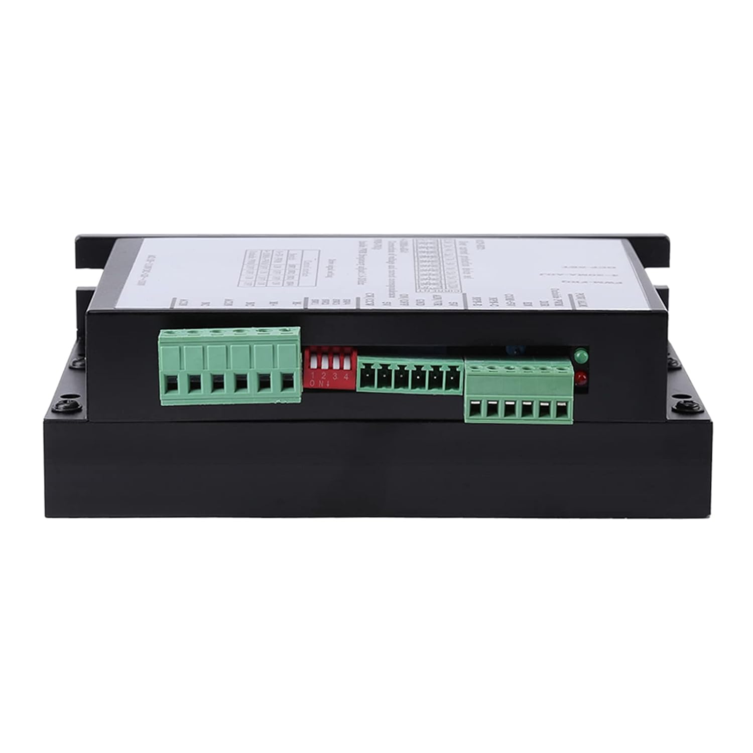
Image 5.1: Side view of the controller, illustrating the various input and output connectors.
5.1. High Voltage Connector
- M+: Motor+ Connect to the positive terminal of the motor.
- M-: Motor- Connect to the negative terminal of the motor. To change rotation direction, exchange the M+ and M- wires.
- NC: This terminal is not used.
- ACIN: Power Input Connect AC power here. Polarity does not need to be distinguished.
- Power Input Range: AC15V-110V (50/60Hz), DC20V-150V.
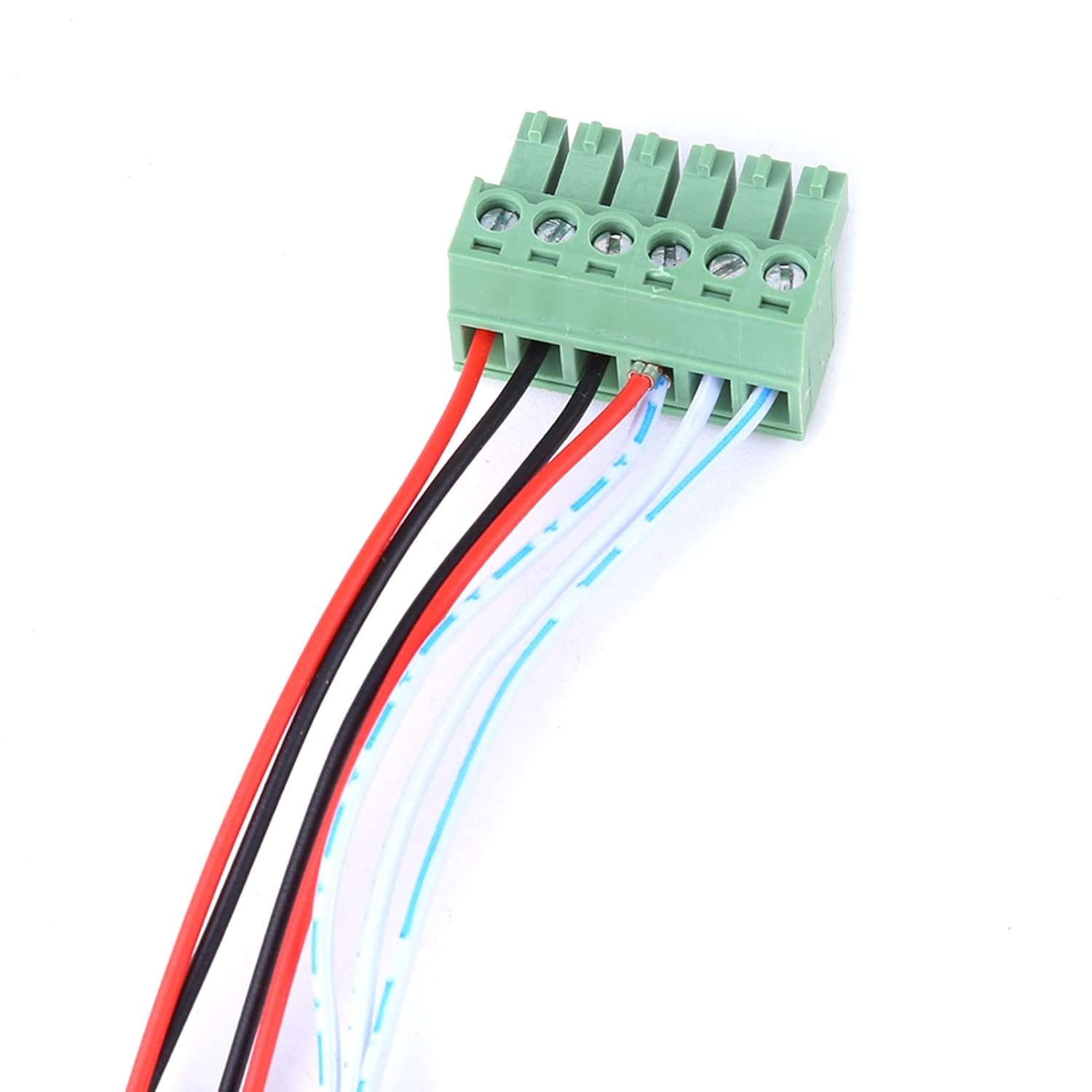
Image 5.2: A close-up view of a typical green terminal block connector used on the controller.
5.2. Analog Input / Digital Control Connector
This connector handles various control signals for speed governing and motor control.
- 5V: Power supply 5V output pin.
- AIN / VR: Analog input pin. This pin connects to signals for speed governing (0-5V/0-10V voltage or 4-20mA current). The 4-digit DIP switch must be set accordingly.
- GND: Common ground. Avoid touching this terminal when power is on.
- ON/OFF: Motor ON/OFF control. Connect to an external switch. When not connected to GND, the motor is ON. When connected to GND, the motor is OFF. The external ON/OFF switch should connect between ON/OFF and GND.
- CW/CCW: Motor CW/CCW rotation control. Connect to an external switch between CW/CCW and 5V. A minimum control interval of ≥1.5 seconds is recommended to protect the motor brush.

Image 5.3: Example of external push buttons that can be used for ON/OFF and CW/CCW control.

Image 5.4: An external potentiometer, which can be used for manual speed control.
5.3. DIP Switch Settings for Drive Signal
The 4-digit DIP switch (SW1, SW2, SW3, SW4) configures the controller for different drive signal types.
| Control Interface | SW1 | SW2 | SW3 | SW4 |
|---|---|---|---|---|
| 0-5V-PWM | ON | OFF | OFF | ON |
| 4-20MA-PWM | OFF | ON | OFF | ON |
| Outside PWM | OFF | OFF | ON | OFF |
5.4. External Control Wiring (PLC / Control Card)
The speed controller can be integrated with a PLC (Programmable Logic Controller) or a control card for automated speed governing.
For PLC Integration:
Set the 4-digit DIP switch to "Outside PWM" (SW1-OFF, SW2-OFF, SW3-ON, SW4-OFF).
- COM+5V: Connect a resistor (1.5kΩ-3kΩ) in series to COM or to the 24V+ power of the PLC.
- Outside PWM: Connect to the PWM IO connector of the PLC.
- DIR: Use a high/low level IO1 connector from the PLC to control direction.
- EN: Use a high/low level IO2 connector from the PLC to enable/disable the motor.
For Control Card Integration:
Set the 4-digit DIP switch to "Outside PWM" (SW1-OFF, SW2-OFF, SW3-ON, SW4-OFF).
- COM + 5V: Connect to the 5V output of the control card.
- Outside PWM: Connect to the PWM output of the control card. Note that some control cards use P1 connector for PWM, while others use P17. Refer to your control card's documentation.
6. Operation
Once the controller is properly installed and wired, you can operate it using various methods.
6.1. Potentiometer Speed Governing
For manual speed control using a 10kΩ potentiometer:
- Connect the three pins of the 10kΩ potentiometer to the 5V, AIN/VR, and GND terminals respectively.
- Set the 4-digit DIP switch to "0-5V - PWM" (SW1-ON, SW2-OFF, SW3-OFF, SW4-ON).
6.2. 0-5V or 0-10V Voltage Signal Speed Governing
For speed control using an external voltage signal:
- Connect the voltage signal to the AIN/VR terminal and the signal ground to the GND terminal.
- Set the 4-digit DIP switch to "0-5V - PWM" (SW1-ON, SW2-OFF, SW3-OFF, SW4-ON).
- For a 0-5V voltage signal input, no external resistor is needed.
- For a 0-10V voltage signal input, two resistors should be added as per standard voltage divider wiring for 0-10V to 0-5V conversion if the controller only supports 0-5V directly. (The provided image implies direct 0-10V input is possible, but mentions adding resistors, which might be for scaling if the AIN/VR is 0-5V max).
6.3. 4-20mA Current Signal Speed Governing
For speed control using an external current signal:
- Connect the current signal to the AIN/VR terminal and the signal ground to the GND terminal.
- Set the 4-digit DIP switch to "4-20MA - PWM" (SW1-OFF, SW2-ON, SW3-OFF, SW4-ON).
6.4. Motor ON/OFF and Direction Control
- ON/OFF: Use an external switch connected between the ON/OFF terminal and GND. When the switch closes (connecting ON/OFF to GND), the motor turns off. When open, the motor is on.
- CW/CCW: Use an external switch connected between the CW/CCW terminal and 5V. This controls the motor's rotation direction. Ensure a minimum control interval of ≥1.5 seconds between direction changes to protect the motor brush.
7. Maintenance
The Walfront AC20-110V PWM Brushed Motor Speed Controller is designed for durability and requires minimal maintenance. However, regular checks can ensure optimal performance and longevity.
- Keep the controller clean and free from dust and debris. Use a soft, dry cloth for cleaning.
- Ensure adequate ventilation around the unit, especially the heat sink, to prevent overheating.
- Periodically inspect all wiring connections for tightness and signs of wear or damage. Loose connections can lead to intermittent operation or electrical hazards.
- Avoid exposing the controller to excessive moisture or corrosive environments.
- If the unit is stored for extended periods, ensure it is in a dry, temperature-controlled environment.

Image 7.1: The heat sink fins on the underside of the controller, crucial for heat dissipation.
8. Troubleshooting
If you encounter issues with your Walfront AC20-110V PWM Brushed Motor Speed Controller, consider the following troubleshooting steps:
- Motor Not Responding:
- Check all power connections to ensure they are secure and receiving the correct voltage.
- Verify the DIP switch settings match your chosen control method (potentiometer, voltage, current, or external PWM).
- Ensure the ON/OFF terminal is not connected to GND (motor should be ON when open).
- Inspect motor wiring for proper connection to M+ and M-.
- Incorrect Speed Control:
- Confirm the DIP switch settings are correct for the analog input signal type (0-5V, 0-10V, or 4-20mA).
- If using a potentiometer, ensure it is correctly wired to 5V, AIN/VR, and GND.
- If using a 4-20mA signal, adjust the 4-20MA-ADJ potentiometer for calibration.
- Motor Overheating or Shutting Down:
- Check the motor's load. The controller supports up to 2kW limit load, 1.5kW nominal.
- Verify the OCP-SET (over-current protection) potentiometer is set appropriately for your motor's current draw.
- Ensure adequate ventilation for the controller's heat sink.
- Direction Control Issues:
- Check the wiring of the CW/CCW switch to the controller.
- Ensure the minimum control interval of ≥1.5 seconds is observed when switching direction.
9. Package Contents
The package for the Walfront AC20-110V PWM Brushed Motor Speed Controller includes:
- 1 x Walfront AC20-110V PWM Brushed Motor Speed Controller
10. Warranty and Support
For warranty information or technical support, please refer to the seller's policies or contact Walfront customer service directly. Keep your purchase receipt for any warranty claims.


