
1. Introduction
This user manual provides comprehensive instructions for the installation, operation, and maintenance of your Audio System CO-600.5 High-Performance 5-Channel Class A/B Amplifier. To ensure optimal performance and safety, please read this manual thoroughly before using the product and retain it for future reference.
2. Safety Information
General Product Safety according to EU Regulation 2023/2028:
- Observe the manufacturer's instructions and operating instructions for switching off the power supply to the vehicle and in the retrofit products.
- The supply line to the retrofit product must not be longer than 30cm from the operating battery.
- Fasten retrofit devices and accessories properly.
- It is recommended that the retrofit devices/accessories be installed by a specialist workshop. Otherwise, product or vehicle damage and fire can occur.
Always disconnect the vehicle's battery before performing any installation or maintenance work to prevent electrical shock or damage.
3. Product Overview
The Audio System CO-600.5 is a high-performance 5-channel Class A/B amplifier designed for car audio systems. It features switchable High-Pass (HP) and Low-Pass (LP) filters, a full active mode, and includes a wired RTC remote control for convenient adjustments. The amplifier supports an input sensitivity range of 0.2V to 6V and includes a high-level RCA input with automatic turn-on capability.
Key Features:
- 5-Channel Class A/B Amplifier
- Switchable High-Pass (HP) and Low-Pass (LP) Filters
- Full Active Mode
- Wired RTC Remote Control Included
- Input Sensitivity: 0.2V - 6V
- High-Level RCA Input with Auto-On
- Power Output: 4 x 60W RMS (4 Ohm) / 4 x 85W RMS (2 Ohm) and 1 x 250W RMS (4 Ohm mono) / 1 x 350W RMS (2 Ohm mono)
Product Views

Figure 3.1: Top view of the CO-600.5 amplifier, highlighting its sleek design and branding.

Figure 3.2: Front view of the amplifier, displaying the cooling fins.
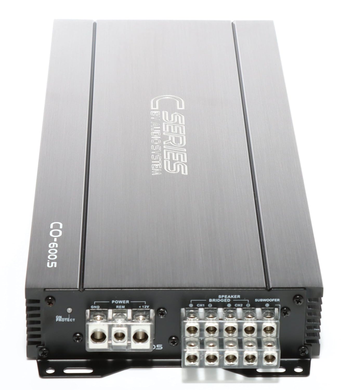
Figure 3.3: Rear view of the amplifier, detailing the power input (GND, REM, +12V) and speaker output terminals.

Figure 3.4: Input and control panel, featuring RCA inputs, gain level adjustments, and crossover frequency controls.
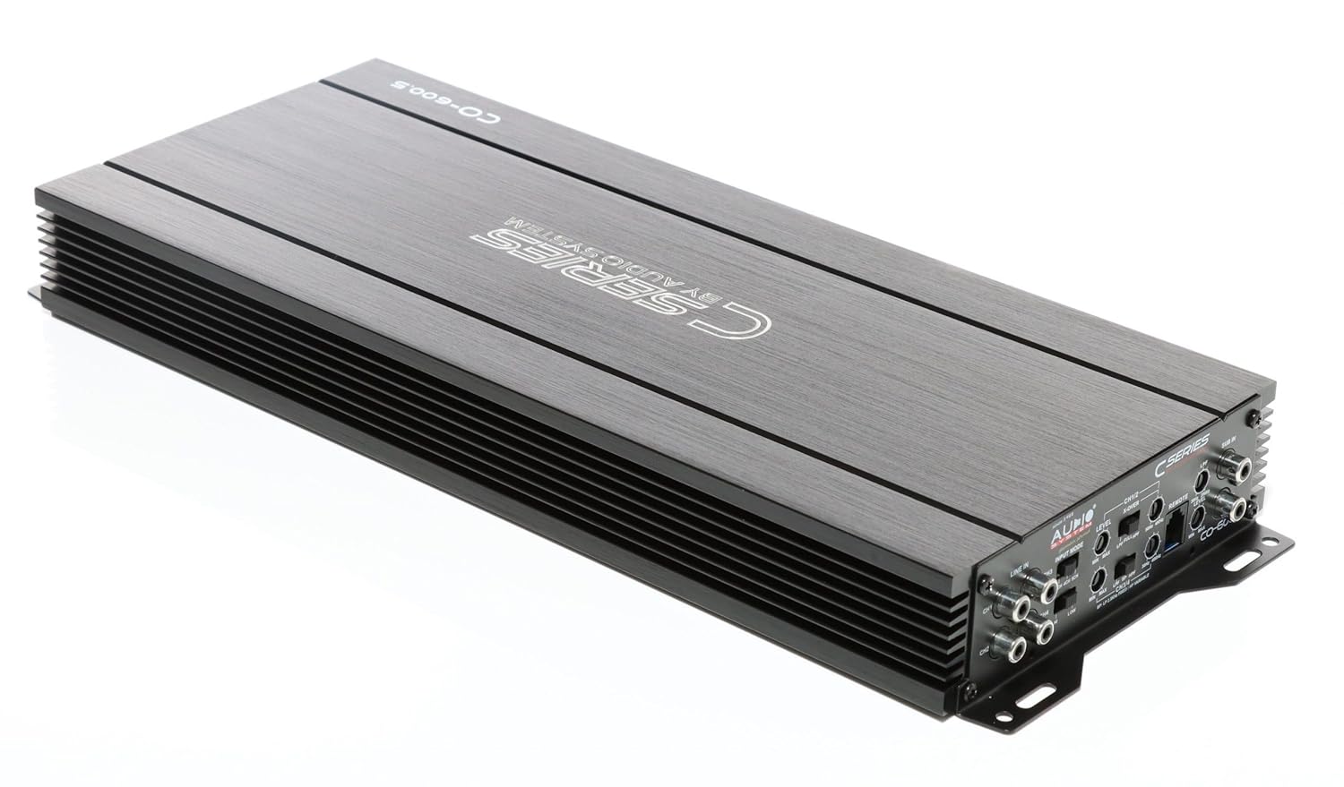
Figure 3.5: Angled view providing a comprehensive look at both connection sides of the amplifier.
4. Setup and Installation
Proper installation is crucial for the performance and longevity of your amplifier. It is highly recommended that installation be performed by a qualified professional.
4.1 Mounting Location
- Choose a dry, well-ventilated location away from direct sunlight and heat sources.
- Ensure sufficient airflow around the amplifier for proper cooling.
- Mount the amplifier securely to a solid surface using appropriate hardware to prevent movement during vehicle operation.
4.2 Wiring Connections
Before making any connections, disconnect the vehicle's negative battery terminal.
- Power (BATT+): Connect a fused power cable directly from the vehicle's positive battery terminal to the +12V terminal on the amplifier. Ensure the fuse is located within 30cm of the battery.
- Ground (GND): Connect a ground cable of the same gauge as the power cable to a clean, unpainted metal surface on the vehicle chassis. The connection point must be free of rust and paint.
- Remote (REM): Connect a remote turn-on wire from your head unit's remote output to the REM terminal on the amplifier. This will turn the amplifier on and off with your head unit.
- RCA Inputs: Connect your head unit's RCA outputs to the amplifier's RCA inputs (CH1/2, CH3/4, SUB IN).
- Speaker Outputs: Connect your speakers to the corresponding speaker output terminals (CH1, CH2, CH3, CH4, SUBWOOFER). Observe correct polarity (+ to + and - to -).
5. Operating Instructions
Once the amplifier is correctly installed and wired, you can proceed with initial setup and operation.
5.1 Initial Power On
- Reconnect the vehicle's negative battery terminal.
- Turn on your head unit. The amplifier should power on automatically via the remote wire. The power indicator LED on the amplifier should illuminate.
5.2 Gain Level Adjustment
The gain control (LEVEL) matches the amplifier's input sensitivity to the output of your head unit. This is not a volume control.
- Set the amplifier's gain control to minimum (fully counter-clockwise).
- Set your head unit's volume to about 75-80% of its maximum.
- Slowly increase the amplifier's gain control until you hear slight distortion, then back it off slightly until the sound is clear.
5.3 Crossover Settings (X-OVER)
The CO-600.5 features switchable HP (High-Pass) and LP (Low-Pass) filters for precise sound tuning.
- HPF (High-Pass Filter): Allows frequencies above the set point to pass through. Use for full-range speakers to prevent low frequencies that can cause distortion.
- LPF (Low-Pass Filter): Allows frequencies below the set point to pass through. Use for subwoofers to prevent high frequencies.
- Adjust the crossover frequencies (e.g., 50Hz-250Hz for HPF, 30Hz-250Hz for LPF) according to your speaker specifications and listening preferences.
5.4 RTC Remote Control
The included wired RTC remote control allows for convenient adjustment of the subwoofer level from the driver's seat.
6. Maintenance
The Audio System CO-600.5 amplifier requires minimal maintenance.
- Keep the amplifier clean and free of dust. Use a soft, dry cloth for cleaning.
- Ensure all connections remain secure. Periodically check wiring for any signs of wear or corrosion.
- Do not use harsh chemicals or abrasive cleaners on the amplifier.
7. Troubleshooting
If you experience issues with your amplifier, refer to the following common problems and solutions:
| Problem | Possible Cause | Solution |
|---|---|---|
| No Power / Amplifier does not turn on |
|
|
| No Sound Output |
|
|
| Distorted Sound |
|
|
If the problem persists after attempting these solutions, please contact Audio System customer support or a qualified car audio technician.
8. Specifications
| Feature | Detail |
|---|---|
| Model Number | 02002CO6005 |
| Channels | 5 (4 full-range + 1 mono/subwoofer) |
| Power Output (RMS) |
|
| Input Sensitivity | 0.2V - 6V |
| Filters | Switchable High-Pass (HP) and Low-Pass (LP) |
| Dimensions (Product) | Approximately 420 x 47 x 171 mm |
| Package Dimensions | 59.99 x 19.99 x 15.01 cm |
| Package Weight | 1 kilogram |
| Voltage (Operating) | 6 Volts (Note: Typically car audio operates at 12V. Please refer to product labeling for exact operating voltage.) |
| Maximum Supply Voltage | 6 Volts |
| Mounting Type | Surface Mount |
9. Warranty and Support
For warranty information, please refer to the documentation provided with your purchase or contact your authorized Audio System dealer. Warranty terms and conditions may vary by region and retailer.
For technical support, service, or inquiries regarding spare parts, please contact Audio System customer service directly or visit their official website. Contact information is typically available on the product packaging or the manufacturer's website.
Manufacturer: Audio System
Manufacturer Address: JRS Labs - The Art of Sound, Heinrich-Heine-Straße 13A, 63329 Rödermark


