
Pro'sKit MT-1233C-C
Pro'sKit MT-1233C-C Digital Multimeter
User Manual
1. Introduction
The Pro'sKit MT-1233C-C is a compact and versatile 3 1/2 digit digital multimeter designed for measuring DC and AC voltage, DC and AC current, resistance, diode, and temperature. It features a clear LCD display with backlight, data hold function, and an anti-shock casing for durability. This manual provides essential information for the safe and effective use of your multimeter.
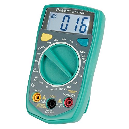
Figure 1: Front view of the Pro'sKit MT-1233C-C Digital Multimeter, showing the display, rotary switch, and input jacks.
Key Features:
- 3 1/2 Digit LCD Display with Backlight
- Measures DC/AC Voltage, DC/AC Current, Resistance, Diode, and Temperature
- Data Hold Function
- Low Battery Indication
- Overload Protection
- Compact and Portable Design with Kickstand

Figure 2: The multimeter shown with its integrated kickstand extended for convenient viewing.
2. Safety Information
Always observe the following safety precautions when using the multimeter:
- Do not exceed the maximum input limits for any range.
- Use extreme caution when working with voltages above 30V AC RMS, 42V peak, or 60V DC. These voltages pose a shock hazard.
- Always disconnect the test leads from the circuit before changing functions or ranges.
- Ensure the correct function and range are selected for the measurement.
- Inspect test leads for damaged insulation or exposed metal before use. Replace if damaged.
- Do not operate the meter if it appears damaged or if the case is open.
- Remove test leads from the meter before opening the battery cover or fuse cover.
- Adhere to local and national safety codes.
3. Product Components and Controls

Figure 3: Labeled diagram of the multimeter's key components and included accessories.
Component Descriptions:
- LCD Display: Shows measurement readings, units, and function indicators.
- Function Button: Used to select specific sub-functions within a range (e.g., AC/DC, Diode/Continuity).
- Backlight Button: Activates or deactivates the display backlight.
- Rotary Switch: Selects the desired measurement function and range.
- VΩmA°C/°F Input Jack: Positive input for voltage, resistance, current (up to 200mA), and temperature measurements.
- COM Input Jack: Common (negative) input for all measurements.
- 10A MAX Input Jack: Positive input for high current measurements (up to 10A).
- Test Leads: Red and black leads for connecting the multimeter to the circuit under test.
- Temperature Probe: K-type thermocouple for temperature measurements.
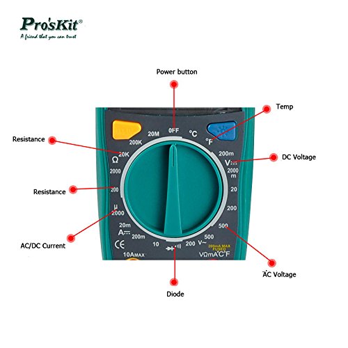
Figure 4: Detailed view of the rotary switch and its measurement functions.
4. Setup and Initial Operation
4.1 Battery Installation
- Ensure the multimeter is turned off and test leads are disconnected.
- Locate the battery compartment cover on the rear of the unit.
- Unscrew the retaining screw(s) and remove the cover.
- Insert two 1.5V AAA batteries, observing correct polarity (+/-).
- Replace the battery cover and secure with the screw(s).
4.2 Connecting Test Leads
- For most measurements (voltage, resistance, temperature, and current up to 200mA), insert the red test lead into the VΩmA°C/°F jack and the black test lead into the COM jack.
- For high current measurements (up to 10A), insert the red test lead into the 10A MAX jack and the black test lead into the COM jack.
4.3 Powering On/Off
Rotate the central rotary switch from the 'OFF' position to any desired measurement function to power on the multimeter. To power off, rotate the switch back to the 'OFF' position.
5. Operating Instructions
5.1 DC Voltage Measurement (V–)
- Connect the red lead to VΩmA°C/°F and the black lead to COM.
- Set the rotary switch to the desired DC Voltage range (e.g., 200m, 2, 20, 200, 500V). If the voltage is unknown, start with the highest range and decrease as needed.
- Connect the test leads in parallel to the circuit or component to be measured.
- Read the voltage value on the LCD display.
5.2 AC Voltage Measurement (V~)
- Connect the red lead to VΩmA°C/°F and the black lead to COM.
- Set the rotary switch to the desired AC Voltage range (e.g., 200, 500V).
- Connect the test leads in parallel to the AC circuit or component.
- Read the voltage value on the LCD display.
5.3 DC/AC Current Measurement (A– / A~)
Caution: Always connect the multimeter in series with the circuit when measuring current. Ensure the circuit is de-energized before connecting the meter.
- For currents up to 200mA, connect the red lead to VΩmA°C/°F. For currents up to 10A, connect the red lead to 10A MAX. Connect the black lead to COM.
- Set the rotary switch to the desired DC or AC Current range (e.g., 200m, 10A).
- Open the circuit where current is to be measured and connect the multimeter in series.
- Apply power to the circuit and read the current value on the LCD display.
5.4 Resistance Measurement (Ω)
- Connect the red lead to VΩmA°C/°F and the black lead to COM.
- Set the rotary switch to the desired Resistance range (e.g., 200, 2k, 20k, 200k, 2M, 20MΩ).
- Ensure the component or circuit is de-energized before measuring resistance.
- Connect the test leads across the component.
- Read the resistance value on the LCD display.
5.5 Diode Test (▶)
- Connect the red lead to VΩmA°C/°F and the black lead to COM.
- Set the rotary switch to the Diode test position.
- Connect the red lead to the anode and the black lead to the cathode of the diode. The display will show the forward voltage drop.
- Reverse the leads. The display should show 'OL' (Overload) for a good diode.
5.6 Temperature Measurement (°C/°F)
- Connect the temperature probe to the VΩmA°C/°F and COM jacks, observing polarity.
- Set the rotary switch to the °C or °F temperature function.
- Place the tip of the temperature probe on or near the object whose temperature is to be measured.
- Read the temperature value on the LCD display.
5.7 Data Hold Function
Press the 'HOLD' button (often integrated with the backlight button or a separate button) to freeze the current reading on the display. Press it again to release the hold and resume live readings.
5.8 Backlight Function
Press the 'LIGHT' button (often integrated with the data hold button) to illuminate the LCD display for better visibility in low-light conditions. Press it again to turn off the backlight.
6. Maintenance
6.1 Cleaning
Wipe the case with a damp cloth and mild detergent. Do not use abrasives or solvents. Keep the input terminals free of dirt or debris.
6.2 Battery Replacement
When the battery symbol appears on the LCD display, the batteries need to be replaced. Follow the steps in Section 4.1 Battery Installation.
6.3 Fuse Replacement
If the current measurement function fails, the fuse may need replacement. The 200mA input is typically fused. Refer to the specifications for the correct fuse type and rating. To replace the fuse:
- Ensure the multimeter is turned off and test leads are disconnected.
- Open the battery compartment cover (as for battery replacement). The fuse is usually located near the battery compartment.
- Carefully remove the old fuse and replace it with a new one of the identical type and rating.
- Replace the cover and secure the screw(s).
6.4 Storage
If the multimeter is not to be used for an extended period, remove the batteries to prevent leakage and damage to the unit. Store the multimeter in a cool, dry place away from direct sunlight and extreme temperatures.
7. Troubleshooting
- No Display or Faint Display: Check battery installation and charge. Replace batteries if necessary.
- Incorrect Readings: Ensure correct function and range are selected. Check test lead connections. Verify the circuit is de-energized for resistance/diode tests.
- Current Measurement Not Working: Check the fuse. Replace if blown. Ensure test leads are connected to the correct current input jack (200mA or 10A).
- 'OL' (Overload) Display: The measured value exceeds the selected range. Switch to a higher range.
8. Specifications
| Specification | Value |
|---|---|
| Item Weight | 2.08 ounces |
| Power Source | Battery Powered (2 x 1.5V AAA) |
| Style | Digital |
| Measurement Type | Ammeter, Multimeter (Voltage, Current, Resistance, Temperature, Diode) |
| Display | 3 1/2 Digit LCD |
| Manufacturer | China |
| Date First Available | September 13, 2018 |
9. Warranty and Support
Warranty information for the Pro'sKit MT-1233C-C Digital Multimeter is typically provided with your purchase documentation. Please refer to the warranty card or contact your retailer for details regarding warranty coverage and terms.
For technical support, troubleshooting assistance beyond this manual, or inquiries about replacement parts, please contact the manufacturer or your authorized Pro'sKit distributor. Contact information can usually be found on the product packaging or the manufacturer's official website.
Ask a question about this manual
Ask about setup, troubleshooting, compatibility, parts, safety, or missing instructions. Manuals+ will review the question and use this page’s manual context to help answer it.